



The traditional manufacturing workflow—moving parts between discrete lathes and mills—introduces inherent inefficiencies, from tolerance stack-up to excessive work-in-progress (WIP) inventory. As component complexity increases in sectors like aerospace and medical devices, relying on multiple setups escalates labor costs, fixture expenses, and the risk of scrapped parts due to re-chucking errors. Transitioning to "done-in-one" manufacturing requires evaluating unified platforms. This guide examines the technical capabilities, implementation realities, and ROI frameworks for adopting a 5 axis turning machine to produce complete components in a single setup. We will look at spindle configurations, tooling requirements, and programming strategies to maximize machine utilization. By understanding the mechanical architecture and software demands of these advanced systems, shop floor managers can effectively eliminate secondary operations and streamline their production pipelines.
Consolidated Operations: Integrating turning and milling into a single multi task turning center eliminates secondary operations, drastically reducing setup times and fixture costs.
Precision and Quality: Machining a complete component in one setup eliminates tolerance stack-up associated with moving parts between different machines.
Software Dependency: The ROI of a 5-axis turning platform is heavily dependent on advanced CAM software and accurate post-processors to manage complex kinematics, coordinate continuous multi-axis toolpaths, and prevent collisions.
High Initial Investment vs. Long-Term Yield: While capital expenditure and operator training requirements are high, the reduction in labor hours, WIP, and scrap often justifies the investment for high-complexity, high-value parts.
Defining the 5 Axis Turning Machine vs. Traditional CNC Platforms
Kinematic Architecture
A modern multi-axis platform operates using X, Y, and Z linear axes combined with rotary axes. You typically see a B-axis milling head and C-axis main or sub-spindles. These movements occur along five different directions simultaneously to maintain optimal tool-to-part contact angles. This continuous synchronization allows the machine to carve complex contours without stopping to reposition the tool. The linear axes ride on heavy-duty roller guideways or hand-scraped box ways to absorb the heavy cutting forces generated during roughing operations. The rotary axes utilize direct-drive torque motors to eliminate backlash and provide instantaneous positioning feedback to the CNC control. This mechanical rigidity directly translates to tighter geometric tolerances on the finished workpiece.
Standard 5-Axis Milling vs. 5-Axis Turning
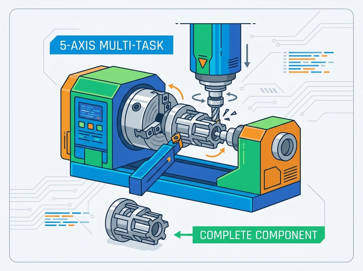
Standard 5-axis milling involves a rotating tool cutting a stationary workpiece, or one pivoting on a tilting table. In contrast, a turning-centric multi task turning center relies on high-RPM part rotation on a spindle as the primary material removal method. A 5-axis milling head supplements this turning capability. This allows complex milling operations on a turned part. When you chuck a piece of bar stock into a turning center, the main spindle generates the surface footage required for turning, grooving, and threading. The milling head then engages to machine flats, drill off-center holes, or cut helical splines. This dual-nature approach requires a massive cast iron bed to dampen the distinct vibration frequencies generated by both turning and milling operations.
Rotary Axis Lexicon (A, B, and C)
Understanding rotary axes is necessary in a turn-mill environment. The nomenclature dictates how the machine approaches the workpiece.
C-Axis: Dynamic rotational indexing of the main and sub-spindles. It provides precise angular positioning for milling features on the face or outer diameter of the part.
B-Axis: Tilting of the milling spindle to machine compound angles. This axis allows the tool to approach the part from virtually any angle, enabling the machining of complex undercuts and angled cross-holes.
A-Axis: Auxiliary rotational axis. Shops often use this for programmable steady rests or tailstocks to support long, shaft-like parts during aggressive turning cycles.
Simultaneous 5-Axis vs. 3+2 Positional Machining
Simultaneous 5-axis toolpaths involve continuous movement of all five axes. You need this for complex organic contours like turbine blades or aerospace impellers. The machine control constantly calculates the tool center point to keep the cutting edge engaged at the correct angle. Conversely, 3+2 indexing locks the B-axis at a specific angle to machine flat faces or drill angled holes. This positional machining maximizes rigidity for heavy cuts. By locking the rotary axes using hydraulic brakes, the machine transforms into a highly rigid 3-axis mill, allowing you to push high feed rates and heavy depths of cut without inducing chatter.
The "Done-in-One" Philosophy
Dual-spindle configurations allow the machine to automatically transfer the part from the main spindle to the sub-spindle. This enables complete machining of front and back faces without manual intervention. The part drops into a catcher fully finished. You eliminate the need for secondary setups. Part transfer requires exact synchronization between the two spindles. They must rotate at the exact same RPM and phase angle while the sub-spindle advances to grip the part. Once clamped, a parting tool separates the component from the main bar stock, and the sub-spindle retracts to finish the back side. This automated handoff is the cornerstone of unattended, lights-out manufacturing.
Core Configurations: Choosing the Right Architecture
The B-Axis Multi Task Turning Center
This design features a dedicated milling spindle mounted on a pivoting B-axis, capable of automatic tool changes (ATC). It handles highly complex geometries, deep angled drilling, and simultaneous 5-axis contouring. Tilting the B-axis allows the use of shorter, more rigid cutting tools. This reduces deflection and chatter while yielding superior surface finishes. The ATC magazine can hold anywhere from 40 to over 120 tools, providing the flexibility to machine entire families of parts without manual tool changeovers. However, it generally has a larger footprint. The milling spindle may also have lower torque for heavy turning compared to a traditional static turret. You must balance the need for milling flexibility against the raw material removal rates required for your specific components.
The Power Turret Turning Milling Machine
This configuration utilizes a robust lower or upper turret equipped with live tooling and Y-axis capabilities. A power turret turning milling machine handles high-volume production where heavy, high-torque turning is the primary operation. Milling requirements are secondary, such as flats, cross-holes, or keyways. The turret indexes rapidly from station to station, minimizing chip-to-chip times. The trade-off is limited angular flexibility compared to a B-axis head. Tool capacity is strictly restricted by the number of turret stations, typically 12 to 24 positions. If your parts require extensive heavy turning with only basic off-center milling, the power turret configuration offers faster cycle times and a more compact machine footprint.
| Feature | B-Axis Multi-Tasking Center | Power Turret Turn-Mill |
|---|---|---|
| Primary Strength | Complex 5-axis milling, deep angled holes | Heavy turning, rapid indexing, high volume |
| Tool Capacity | High (40 - 120+ via ATC) | Limited (12 - 24 via Turret) |
| Milling Rigidity | Excellent for varied angles (shorter tools) | Good for orthogonal features (X/Y/Z) |
| Turning Torque | Moderate (spindle housing limitations) | High (massive turret casting) |
| Footprint | Large | Compact |
Technical Evaluation Criteria: Features to Manufacturing Outcomes
Geometric Capabilities: Prismatic vs. Axisymmetrical Parts
Analyze part geometries to determine machine selection. Prismatic-heavy components with minor turned features favor 5-axis milling centers. Axisymmetric or shaft-like parts with complex eccentric features require a dedicated turning platform to handle the heavy rotational cutting efficiently. Look at your part prints. If the component starts as a square block and requires mostly face milling and pocketing, a trunnion-style mill makes sense. If it starts as round bar stock and requires extensive OD turning, threading, and boring before the milling features are added, a turn-mill center is the correct choice. Matching the machine architecture to the raw material shape minimizes wasted cutting time.
Spindle Power, Torque, and Rigidity
Evaluate continuous versus peak power ratings for both the turning spindle and the milling head. Assess machine bed construction, such as cast iron or polymer concrete. Compare box way versus linear guide designs. These factors determine vibration dampening during interrupted cuts in exotic alloys. A high-torque main spindle with a built-in gearbox provides the low-end grunt needed to rough out large diameter forgings. Conversely, a high-speed, direct-drive milling spindle provides the RPM necessary for small-diameter end mills and drills. The machine bed must absorb the harmonic vibrations generated by these different cutting dynamics to prevent chatter marks on the finished part.
Tool Management and Automation
Analyze Automatic Tool Changer (ATC) capacity. Complex parts often require 40 to 120 or more tools. Evaluate tool wear monitoring systems and redundant tool management capabilities. These features support lights-out manufacturing and minimize operator intervention. When a cutting tool reaches the end of its predictable life, the CNC control must automatically swap it for a sister tool without stopping the cycle. Laser tool presetters inside the machine envelope measure tool length and diameter offsets automatically, compensating for thermal growth and edge wear. This closed-loop feedback system ensures dimensional accuracy across large production batches.
Thermal Stability and Coolant Management
Active chiller systems for spindles and ball screws maintain micron-level precision over long, uninterrupted production runs. High-pressure coolant delivery systems, often reaching 1,000 PSI, are necessary for effective chip evacuation in deep-hole drilling and exotic material machining. As the machine runs, friction generates heat in the bearings and guideways. This heat causes the metal components to expand, shifting the tool position relative to the workpiece. Chilled coolant circulating through the machine castings stabilizes the internal temperature. High-pressure coolant blasts chips out of deep cavities, preventing recutting and premature tool failure. It also breaks stringy chips into manageable pieces, preventing them from wrapping around the chuck or tooling.
Business Impact and ROI Considerations
Labor and Setup Reduction
Consolidating operations shifts the workflow from multiple operators managing several machines to a single operator managing a multi-tasking cell. This reduces labor hours and setup times. Instead of moving a batch of parts from a lathe to a mill, and then to a deburring station, the operator loads raw material and unloads finished components. This single-setup approach eliminates the time spent tramming vises, dialing in fixtures, and touching off tools on multiple machines. The operator can focus on process optimization, quality control, and programming the next job while the machine runs unattended.
WIP and Floor Space
Eliminating WIP inventory sitting between operations reduces required factory floor space. When parts move through multiple discrete machines, they often sit in bins waiting for the next available spindle. This ties up capital in unfinished goods and clutters the shop floor. A unified turn-mill platform converts raw stock into finished parts in one continuous cycle. You can ship parts immediately after they come off the machine, improving cash flow and reducing the physical footprint required for storage racks and staging areas.
Agility in High-Mix, Low-Volume (HMLV)
Quick changeover capabilities, pre-loaded tool carousels, and standardized workholding make these machines highly profitable for short-run, complex parts. In an HMLV environment, setup time is the enemy of profitability. By keeping a standard array of turning and milling tools resident in the ATC magazine, you eliminate the need to tear down and rebuild tool assemblies for every new job. Standardized collet chucks and zero-point quick-change jaw systems allow the operator to swap workholding in minutes rather than hours. This agility allows the shop to take on smaller batch sizes profitably and respond quickly to urgent customer demands.
Industry-Specific Applications and Compliance
Aerospace and Defense
Machining exotic alloys like Titanium and Inconel requires high rigidity and low cutting speeds. Producing complex turbine blades, engine shafts, landing gear components, and structural elements with simultaneous 5-axis contouring helps meet strict AS9100 tolerances. Knowing when to route an aerospace part to a 5-axis mill versus a multi-tasking turn-mill depends heavily on the ratio of turning to milling required. Aerospace components often feature thin walls and deep pockets that are prone to distortion. The ability to machine these features in a single setup, without releasing the clamping pressure, ensures the part remains dimensionally stable. High-pressure coolant is mandatory to control the heat generated when cutting heat-resistant superalloys.
Medical Device Manufacturing
Swiss-style turning applications are common for bone screws, spinal cages, and dental implants. Meeting FDA compliance requires repeatable, single-setup processes. These unified platforms reduce human handling, clamping distortion, and surface contamination risks. Medical parts are typically small, highly complex, and machined from tough materials like 316L stainless steel or titanium. The sub-spindle capabilities of a turn-mill center allow for the complete machining of the back-end features, such as Torx drives or cannulated holes, without manual intervention. This automated process guarantees lot-to-lot consistency and simplifies the validation procedures required for medical device manufacturing.
Implementation Risks and Mitigation Strategies
Programming Complexity
Standard CAM packages lack the capability to safely program multi-channel, multi-spindle operations. Invest in specialized multi-tasking CAM software and demand verified, machine-specific post-processors. Programming a machine with two spindles, two turrets, and a B-axis head requires software that can synchronize the toolpaths to prevent collisions and optimize cycle times. The post-processor must accurately translate the CAM data into the specific G-code dialect required by the machine control. Do not attempt to run a complex turn-mill center with basic 3-axis milling software.
Collision Risks in Dense Work Envelopes
The high cost of spindle crashes due to the proximity of turrets, sub-spindles, steady rests, and B-axis heads is a significant risk. Mandate the use of digital twin simulation software to verify G-code toolpaths before physical machining occurs. The work envelope of a multi-tasking machine is extremely crowded. A minor programming error can cause a catastrophic collision between the milling head and the sub-spindle chuck. Simulation software reads the actual G-code and models the machine kinematics in a virtual environment, highlighting any potential interference issues before you press cycle start on the shop floor.
Operator Skill Gap
Traditional lathe or mill operators struggle with complex kinematics. Budget for comprehensive, vendor-led training programs and transition to a programmer-operator model. Running a 5-axis turn-mill requires a deep understanding of both turning and milling principles, as well as advanced CNC control navigation. Operators must know how to manage tool center point control, dynamic work offsets, and multi-channel synchronization codes. Invest heavily in training to ensure your staff can safely and efficiently operate these advanced manufacturing platforms.
Conclusion
Compile a portfolio of your most complex, bottleneck-prone parts to evaluate current inefficiencies and determine the exact ratio of turning to milling required.
Request time studies, turnkey proposals, and physical test cuts from shortlisted machine tool builders to validate cycle times, surface finish, and precision claims on your specific materials.
Audit your current CAM software capabilities and budget for advanced multi-tasking programming packages and digital twin simulation tools prior to machine delivery.
Develop a comprehensive training matrix for your setup personnel and operators to bridge the skill gap between traditional 2-axis turning and simultaneous 5-axis machining.
FAQ
Q: What is the difference between a 5 axis turning machine and a 5-axis mill?
A: A 5-axis turning machine primarily rotates the workpiece at high speeds for lathe operations while utilizing live tooling or a milling head for secondary features. A 5-axis mill keeps the workpiece relatively stationary or on a tilting rotary table while the rotating cutting tool moves around it.
Q: Can a multi task turning center completely eliminate secondary operations?
A: Yes. By utilizing a main spindle and a sub-spindle, the machine can automatically transfer the part to machine the back face, dropping a fully completed component into the parts catcher without manual re-chucking.
Q: What software is required to run a power turret turning milling machine?
A: You need an advanced CAM system capable of multi-channel synchronization, along with a highly accurate, machine-specific post-processor to translate the program into safe G-code.
Q: Are 5-axis turning machines suitable for high-volume production?
A: While traditionally used for high-mix, low-volume complex parts, integrating bar feeders, gantry loaders, and robotic part unloaders makes them highly effective for automated, high-volume production runs.
Q: How does 5-axis turning improve part accuracy?
A: By machining all features in a single setup, the machine eliminates tolerance stack-up which naturally occurs when a part is manually unclamped, moved, and re-clamped into a different machine tool.
Q: What are the primary axes in 5-axis turning?
A: Typically, the axes include X, Y, and Z for linear movements, a C-axis for indexing and rotation of the main or sub-spindles, and a B-axis for pivoting the milling head or live tooling on a Y-axis turret.
Related Articles
-
 Dear Customers and Business Partners,In order to strictly comply with national export control laws and regulations, and to fulfill international obligations, ensuring that our exported CNC milling machines and CNC lathes are fully legal and compliant, we hereby notify you of the relevant policies coCompany News
 -
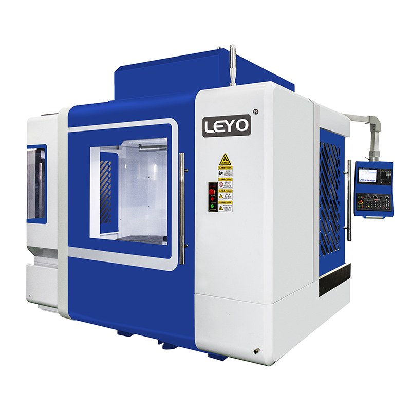 Eliminate part deflection and chatter. Master expert workholding strategies for vertical milling machines to maximize CNC precision and reduce scrap.Product news
 -
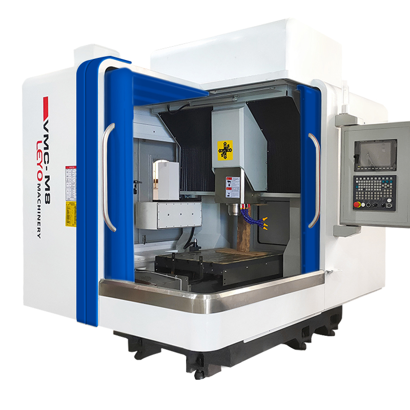 Stop tool breakage and scrap parts. Discover how horizontal milling machines use gravity for flawless chip evacuation and maximum ROI.Product news


