



Walk across any busy machining floor, and you will eventually hear it. The sharp, expensive snap of a broken tap. Scrapped parts pile up. Production schedules slip. The intensely frustrating process of manual tool extraction begins. These shop floor nightmares usually stem from a fundamental mismatch between a machine's mechanical capabilities and the specific threading requirements of the job. Push a spindle beyond its low-end torque limit, and the tool binds. The result is inevitably scrap.
To solve this, modern manufacturers turn to the specialized drill tap center. This is a highly agile piece of equipment designed as the ultimate solution for high-speed, precision hole-making. Unlike traditional heavy-duty mills built strictly for brute force, these machines are engineered to maximize throughput for specific thread sizes. Understanding the exact rotational forces these machines can handle is the absolute key to optimizing your production runs, extending tool life, and protecting your profit margins.
Key Takeaways
Torque Capacity Varies by Spindle: Standard BT30 or BBT30 models comfortably handle continuous tapping up to M16 in aluminum alloys and M12 in mild steel. Advanced high-torque configurations push these boundaries even further.
Synchronization is Mandatory: Modern synchronous feed technology electronically locks spindle rotation with the Z-axis feed rate. This precision drastically reduces torsional stress and prevents catastrophic tap breakage.
Material and Geometry Matter: The exact torque required is heavily dictated by workpiece material hardness, thread pitch, and tap geometry. Form taps demand significantly more power than traditional cut taps.
Speed vs. Power: A standard heavy-duty mill delivers higher raw torque for large-diameter threading. However, a specialized tapping machine provides superior acceleration, rapid spindle reversal, and energy efficiency for small-to-medium threads.
What is a Drilling Tapping Center and Why Torque Matters
A drilling tapping center is a lightweight, highly specialized CNC machine engineered specifically for rapid hole-making, threading, and light-to-medium milling operations. Typically equipped with a BT30 or BBT30 dual-contact spindle, these machines are designed with low-inertia components. This kinematic profile allows the spindle to accelerate to maximum RPM and brake to a complete stop in mere fractions of a second.
The evolution of this equipment stems directly from the mechanical limitations of traditional vertical mills. Standard mills feature massive cast-iron frames and heavy BT40 or BT50 spindles designed to absorb severe milling vibrations. They possess immense continuous torque. Yet, their high inertia makes them sluggish during the frequent start-stop-reverse cycles required for tapping hundreds of holes. Tapping centers prioritize explosive acceleration. High-end models routinely exceed 1.5G acceleration and execute tool changes in under 1.2 seconds.
Understanding torque limitations within this context is a critical engineering requirement. Torque is the rotational force delivered by the spindle motor. If a machine lacks the necessary low-end grunt for a specific tap size and material combination, the spindle will stall mid-cut. The tool will snap inside the workpiece. Conversely, assuming you always need a massive high-torque machine for M8 holes in aluminum results in purchasing oversized equipment. This leads to wasted floor space, higher power consumption, and significantly slower cycle times.
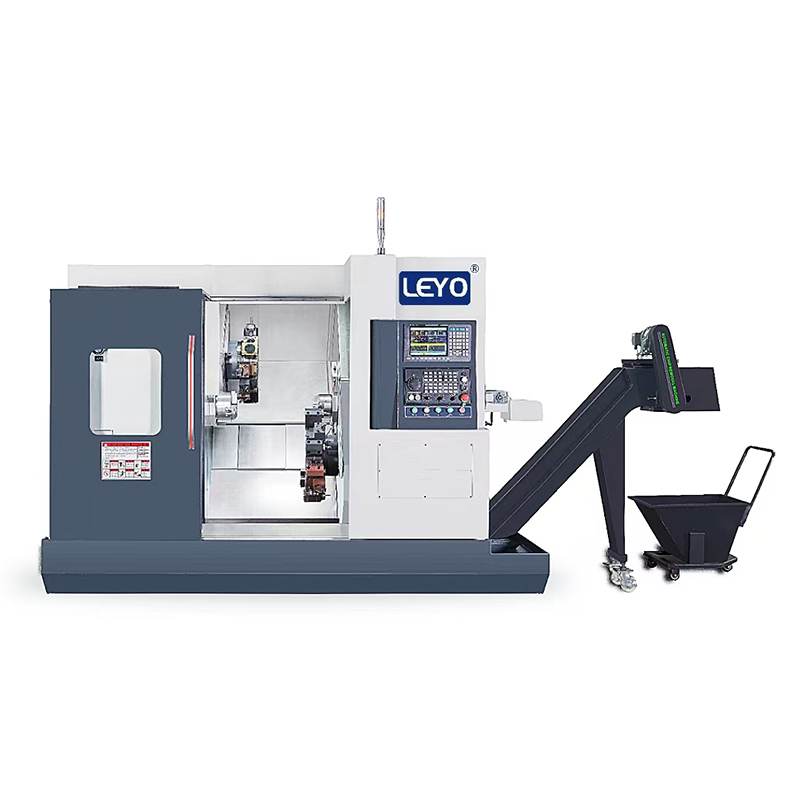
Understanding Tapping Torque in CNC Drilling and Machining
To properly evaluate machine specifications, programmers and operators must grasp the underlying physics of thread creation. During complex cnc drilling and threading sequences, tapping torque refers to the rotational force required to drive a tool through a pre-drilled hole. This force must actively overcome the shear strength of the workpiece material alongside the intense friction generated between the tool flanks and the part.
Furthermore, torque is never a constant metric during the machining cycle. As engineers, we must account for severe torque spikes that occur at highly specific moments. The most critical spike happens at the very bottom of a blind hole. The spindle must rapidly decelerate to zero, reverse its direction, and accelerate backward to extract the tap. During this instantaneous reversal, the machine must overcome both the mechanical binding of packed chips and the physical inertia of the spindle motor itself.
The specific type of tap utilized also fundamentally alters the torque equation. Cut taps feature flutes with sharp cutting edges that shear material away to form the thread profile. Because they remove material in the form of chips, they generate lower cutting resistance and require significantly less torque. Form taps, or roll taps, cold-work the metal instead of cutting it. They displace the solid material outward to form the thread. Since no material is evacuated, the friction and displacement forces are immense. Form tapping typically requires 50 to 100 percent more torque than cut tapping for the exact same thread size.
Exactly What Tapping Torque Do Drilling Tapping Centers Handle?
The torque capacity of any machine is directly tied to its spindle motor specifications, drive mechanism, and continuous power output curve. Standard BT30 or BBT30 spindles typically offer continuous torque ratings ranging from 15 Nm to 35 Nm. Peak torque, which can be sustained for short durations, often reaches up to 50 Nm or more depending on the servo motor size.
In practical manufacturing environments, this translates to specific thread size limitations. High-performance models, like those featuring 20,000 RPM direct-drive spindles and 21-tool servo magazines, are optimized for specific ranges. The table below outlines the generally accepted maximum tapping capacities for a standard 30-taper machine.
| Workpiece Material | Hardness Range | Max Cut Tap Size | Max Form Tap Size | Estimated Torque Req. Max |
|---|---|---|---|---|
| Aluminum Alloys like 6061 | 30 - 95 HB | M20 - M24 | M16 | 15 - 20 Nm |
| Mild Steel like 1018 | 120 - 150 HB | M12 - M14 | M10 | 25 - 30 Nm |
| Stainless Steel like 304 | 150 - 200 HB | M10 | M8 | 28 - 35 Nm |
| Titanium or Hardened Steel | 30+ HRC | M8 | Not Recommended | 30 - 35+ Nm |
Note: These values are empirical estimates. Actual limits depend heavily on thread pitch, coolant pressure, and the specific spindle motor curves of the equipment.
Because tapping operations generally occur at lower spindle speeds, typically between 500 and 2,000 RPM, the critical metric is the machine's base speed torque. A high-quality machine will maintain a flat, steady torque curve at these lower speeds. This ensures the spindle does not stall when the tool bites into the material.
Key Factors That Influence Your Tapping Torque Requirements
Determining whether a specific machine can handle your production run requires analyzing the variables that generate cutting resistance. Torque fluctuates dramatically based on several engineering factors on the shop floor.
Workpiece Material Hardness and Specific Cutting Force
The physical properties of the workpiece dictate the baseline rotational force required. Engineers use a metric called Specific Cutting Force, or Kc, to calculate this. Soft, non-ferrous materials like die-cast aluminum or brass have low Kc values. They shear easily and generate minimal spindle load. Tough alloys like 316 Stainless Steel tend to work-harden during machining. As the tap engages, the material's resistance increases exponentially. This demands maximum low-end torque from the motor.
Tap Size and Thread Pitch
The mathematical relationship between tap diameter and torque is exponential, not linear. Driving an M12 tap requires significantly more than twice the torque of an M6 tap. The thread pitch impacts the volume of material removed per revolution. Coarse pitches take a deeper bite into the metal. They generate larger chips and require substantially more rotational force than fine-pitch threads of the exact same diameter.
Hole Depth and Chip Evacuation
Deep-hole tapping introduces severe friction into the equation. This occurs when the thread depth exceeds 2.5 times the tool diameter. As the tool plunges deeper, chips must travel further up the flutes to escape. If chips pack tightly into the flutes, radial friction against the hole walls spikes. This causes a massive surge in torque. To mitigate this dangerous load, programmers utilize peck tapping cycles where the tool retracts incrementally to break and clear chips.
Coolant and Lubrication
Friction is the ultimate enemy of torque management. Applying high-quality cutting fluid drastically reduces the coefficient of friction between the tool flanks and the workpiece. Modern machining utilizes Through-Spindle Coolant systems. These systems blast high-pressure fluid directly through the center of the tool. This lubricates the cutting edges and forcefully ejects chips from blind holes, keeping the torque requirement stable throughout the entire cycle.
Tool Wear and Geometry
A brand-new, razor-sharp tap slices through material efficiently. As the cutting edges dull from continuous use, the tool begins to rub and push the material rather than cutting it cleanly. This rubbing action severely increases the required cutting force. A dull tap can easily double the torque load on the spindle. Monitoring spindle load meters is essential. An unexplained rise in torque usually indicates the tool has reached the end of its usable life.
Industry Trends: The Shift Towards High-Torque, Low-Inertia Spindles
The manufacturing landscape is rapidly evolving. This shift is driven largely by the automotive transition toward Electric Vehicles and the global expansion of 5G telecommunications. These industries require millions of lightweight components made from die-cast aluminum and magnesium. They demand unprecedented hole-making speeds. Consequently, industry data shows a distinct trend. Machine builders are moving away from traditional belt-driven systems in favor of advanced direct-drive spindles.
These modern direct-drive motors are engineered to eliminate mechanical backlash. More importantly, they deliver a much flatter torque curve at lower RPMs. This technological leap allows workshops to maintain the lightning-fast acceleration needed for short cycle times while providing enough low-end grunt to tap tougher emerging alloys. By bridging the gap between speed and power, today's compact machines are successfully taking on aerospace and medical device tasks that were previously reserved for much heavier, slower equipment.
The Critical Role of Rigid Tapping in Torque Management
In modern high-volume manufacturing, the implementation of rigid tapping is a non-negotiable feature. This process, also known as synchronous feed tapping, occurs when the machine's CNC controller utilizes high-resolution encoders. It perfectly synchronizes the spindle's rotational angle with the linear feed of the Z-axis. For every single revolution of the spindle, the Z-axis advances exactly one thread pitch.
Before the advent of this robust technology, older equipment suffered from micro-lags in servo response. To prevent the tool from tearing the threads or snapping due to synchronization errors, operators were forced to use tension-compression floating tap holders. These holders contained internal springs that allowed the tool to physically pull out or push in slightly, compensating for the machine's mechanical lag.
Synchronous feed technology eliminates the need for floating holders. Tools can now be clamped securely in solid collets or shrink-fit chucks. By maintaining perfect synchronization, it prevents axial pushing or pulling forces from converting into excessive radial torque. This precise control eliminates torque spikes caused by mechanical binding, extends tool life by up to 100 percent, and allows the machine to safely execute threading cycles at significantly higher RPMs.
Drilling Tapping Center vs. Standard Machining Center: Which Do You Need?
Choosing between investing in a nimble tapping machine or a robust, heavy-duty machining center requires a strict analysis of your shop's primary production bottlenecks. Both are capable CNC mills, but their kinematic designs serve entirely different operational purposes.
The Heavyweight: Standard VMC BT40 or BT50
A standard vertical mill is built for brute force. Equipped with heavy-duty box ways or large linear guides and massive spindle motors, these machines easily generate over 100 Nm of torque. They are the correct choice if your primary operations involve heavy material removal, like face milling steel blocks, or tapping large diameter holes M20 and above in ferrous metals. The trade-off is speed. The heavy spindle takes much longer to accelerate, and tool changes often consume 3 to 5 seconds.
The Sprinter: Drilling Tapping Center BT30 or BBT30
This equipment is optimized for high-volume, low-cycle-time production. While its peak torque is lower, its agility is unmatched. Tool changes occur in roughly 1.2 seconds. The spindle can jump from zero to 10,000 RPM in milliseconds. If your parts require dozens of small drilled and tapped holes, such as electronic heatsinks or automotive housings, the cycle time savings will drastically outweigh the lower maximum torque capacity.
How to Choose the Right Equipment for Your Torque Needs
Selecting the correct equipment requires a pragmatic assessment of your worst-case manufacturing scenarios. Do not just look at the brochure. Follow these engineering guidelines to ensure your machine matches your shop floor reality.
First, identify the largest tap size, the coarsest thread pitch, and the toughest material you plan to run in high volumes. Use tooling manufacturer charts to calculate the estimated rotational force required for that specific operation.
Next, carefully review the spindle motor graph provided by the machine builder rather than just looking at the maximum horsepower rating. Horsepower is simply a calculation of torque multiplied by speed. A machine might boast high horsepower at 10,000 RPM but completely lack the low-end torque curve necessary to drive an M12 tap at 800 RPM. Ensure the continuous torque curve remains flat and robust in the lower RPM ranges.
Finally, partner with reliable manufacturers who build machines with rigid cast-iron frames. Look for equipment featuring high-speed direct-drive spindles and fast servo-driven tool magazines. The frame must be capable of absorbing torsional stress without transferring vibration to the cutting tool.
Conclusion
While a specialized tapping machine may not possess the brute force of a heavy-duty mill, its torque capacity is more than sufficient for the vast majority of modern manufacturing needs. By perfectly balancing high-speed acceleration with adequate low-end rotational force, these machines drastically reduce cycle times on small-to-medium parts.
Pairing the right spindle motor with synchronous feed technology prevents broken tools, eliminates scrapped parts, and maximizes workshop profitability. Always evaluate your specific material hardness and thread geometry. Check the spindle motor graph before purchasing. If you are looking to upgrade your shop's efficiency and eliminate tapping bottlenecks, explore the high-performance CNC solutions available at Leyo Machinery to align your equipment perfectly with your production goals.
FAQ
What is the maximum tap size a standard BT30 machine can handle?
Typically, a standard 30-taper machine can comfortably handle up to M16 or M20 in soft materials like aluminum, and up to M12 in mild steel. However, this depends heavily on the specific spindle motor's torque curve, whether you are using a cut tap or a form tap, and the exact thread pitch.
Does synchronous feed tapping require more torque than using a floating tap holder?
No, it is actually the opposite. Synchronous feed optimizes the cutting process by perfectly matching the feed and speed. This eliminates the dragging, binding, and misalignment that frequently occur with floating holders. It actively reduces unnecessary mechanical stress and prevents dangerous torque spikes.
Can I use a tapping center for light milling operations?
Yes. While they are highly optimized for fast hole-making, they are essentially high-speed CNC mills. They are highly capable of light to medium milling tasks, face milling, and contouring, especially in softer materials like aluminum and brass. Operators simply need to ensure they do not exceed the continuous torque ratings during heavier roughing passes.
How do I calculate the required tapping torque for my specific job?
Tapping torque depends on a complex engineering formula involving the tool diameter, thread pitch, the material's specific cutting force, and the tool's geometry. Because manual calculation is highly complex, most major tooling manufacturers provide free online machining calculators or technical charts that accurately estimate the required torque based on your exact parameters.
Why does my CNC machine stall during tapping?
A spindle stalls during tapping when the cutting resistance exceeds the motor's available low-end torque. This often happens if you are running a tap that is too large for the machine's specifications, using a dull tool, or tapping tough materials at an RPM where the spindle motor lacks sufficient power. Switching to a finer thread pitch or using a high-lubricity coolant can help reduce the load.
How do I prevent tap breakage in deep blind holes?
Preventing tap breakage in deep holes requires managing chip evacuation and friction. Utilize peck tapping cycles to break chips into smaller, manageable pieces. Additionally, ensure your coolant concentration is correct and consider using through-spindle coolant to forcefully flush chips out of the hole before they can pack and bind the tool.
Related Articles
-
 Dear Customers and Business Partners,In order to strictly comply with national export control laws and regulations, and to fulfill international obligations, ensuring that our exported CNC milling machines and CNC lathes are fully legal and compliant, we hereby notify you of the relevant policies coCompany News
-
 Abrasive graphite dust destroys standard CNCs. Learn why specialized dust-proof machines and proper wet or dry milling methods are essential for safe EDM electrode production.Product news
-
 Drill tap centers deliver high-speed threading for high-volume production. Understanding spindle torque limits prevents costly tool breakage and optimizes machine cycle times.Product news


