



Misaligning machining technology with production requirements severely impacts manufacturing operations. You risk bottlenecked throughput, excessive tooling wear, and wasted capital expenditure. Production managers and technical buyers face distinct challenges when transitioning from manual operations. You must evaluate equipment for specific part geometries, scale production volumes, and meet strict tolerance standards. Selecting the wrong machine tool compromises part quality and operational efficiency on the shop floor.
We provide a rigorous, technical comparison between milling and turning platforms. Understanding the fundamental differences in kinematics, tooling, and setup requirements establishes a clear framework for procurement. This guides process planning, optimizes workflow automation, and ensures you deploy the right technology for your specific manufacturing outcomes. By analyzing part prints and production volumes, you can match the exact machine architecture to your daily operational demands.
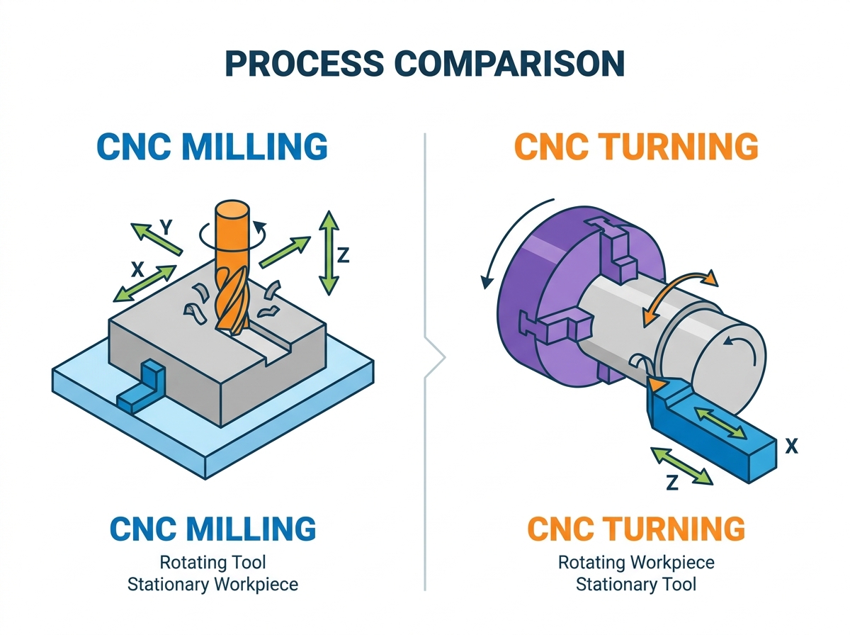
Kinematic Difference: A CNC milling machine utilizes rotating cutting tools against a stationary (or multi-axis positioned) workpiece, whereas a CNC lathe machine rotates the workpiece against stationary cutting tools.
Geometric Suitability: Milling is engineered for prismatic, flat, and complex irregular 3D shapes; turning is optimized for cylindrical, conical, and symmetrical profiles.
Cost & Complexity: Milling generally requires higher initial capital expenditure and more complex CAM programming, while lathes offer faster cycle times for round parts at a lower barrier to entry.
The Automation Leap: Moving from manual milling or turning to CNC configurations dramatically reduces time consumption and human-error-induced scrap while scaling dimensional accuracy.
Hybrid Alternatives: Advanced manufacturing often bridges the gap with mill-turn centers (lathes with live tooling), requiring a nuanced ROI evaluation before purchase.
Defining the Core Mechanics: Operating Principles
The CNC Milling Machine: Rotating Tools, Stationary Workpiece
A CNC Milling Machine operates on a fundamental principle: the cutting tool rotates while the workpiece remains stationary. The machine spindle holds the tool and drives it at high speeds. Standard configurations utilize three linear axes. The X-axis moves left and right, the Y-axis moves forward and backward, and the Z-axis moves up and down. Advanced 4-axis and 5-axis machines introduce rotary axes (A, B, or C) to manipulate the workpiece orientation during the cutting cycle.
Workholding is critical in milling operations. You secure the raw material to the machine bed using precision vises, step clamps, or custom-machined fixturing plates. This rigid setup prevents vibration and ensures dimensional accuracy. Standard milling operations include face milling to create flat surfaces, profile milling for exterior contours, drilling for precise hole making, and pocketing to hollow out internal cavities. When machining a block of 6061 aluminum, for example, the operator might use a 3-inch face mill to square the top surface before dropping in a 1/2-inch solid carbide end mill to rough out a deep pocket.
To execute a successful milling setup, operators typically follow these steps:
Clean the machine table and vise jaws to remove all chips and debris.
Indicate the fixed vise jaw to ensure it is perfectly parallel to the X-axis travel.
Secure the raw stock in the vise, using parallels to elevate the material to the correct height.
Load the required cutting tools into the automatic tool changer (ATC) magazine.
Touch off each tool to establish the tool length offsets in the machine control.
Use an edge finder or spindle probe to locate the X and Y datums on the workpiece.
Run the program in single-block mode with rapid overrides reduced to verify the toolpath safely.
The CNC Lathe Machine: Rotating Workpiece, Stationary Tools
A CNC lathe machine reverses the kinematic relationship. The machine secures the raw material in a chuck or collet attached to the main spindle. The spindle spins the bar stock or billet at high revolutions per minute (RPM). The cutting tools remain stationary and mount to a rigid tool turret.
The turret moves along two primary axes. The Z-axis travels parallel to the spinning workpiece, while the X-axis moves perpendicular to control the cutting depth. This motion shapes the exterior or interior of the spinning part. Standard turning operations include facing to square the end of the part, turning to reduce the outer diameter, grooving to cut channels, threading for fasteners, and boring to enlarge internal holes. When turning a 4140 steel shaft, the continuous engagement of a carbide insert shears the material away efficiently, generating long, continuous chips if the feed rate and depth of cut are optimized.
Part Geometry and Production Capabilities
When to Specify a CNC Milling Machine
You specify a milling center when part geometry demands multi-directional material removal. Success criteria include parts requiring asymmetrical features, flat planar surfaces, or off-center holes. Milling excels at generating complex irregular 3D contours. Typical applications include aerospace brackets, injection mold cavities, automotive engine blocks, and complex medical implants. The rotating tool can approach the material from virtually any angle on a 5-axis setup.
However, milling has distinct limitations. It is highly inefficient for producing perfectly round, long cylindrical parts. Creating a cylinder on a mill requires circular interpolation. This process relies on simultaneous X and Y axis movements, which cannot match the inherent roundness generated by a spinning lathe spindle. Setup times also increase when attempting to machine cylindrical profiles on a mill, as you often need custom soft jaws or a 4th-axis rotary indexer to access multiple sides of the cylinder.
When to Specify a CNC Lathe Machine
You specify a turning center for components requiring rotational symmetry. Success criteria involve parts demanding strict concentricity, conical forms, precise threading, or uniform symmetrical profiles. Lathes dominate the production of shafts, custom bushings, threaded fasteners, hydraulic pistons, and alignment pins. The continuous engagement of the cutting tool against the spinning material yields exceptional surface finishes on round parts.
Standard 2-axis lathes face severe limitations with non-cylindrical features. They cannot machine flat planes, off-center features, or irregular profiles. Producing a hex head on a turned shaft requires transferring the part to a milling center for secondary operations, which increases handling time and introduces tolerance stacking risks. Operators must carefully indicate the part in the mill vise to ensure the hex aligns perfectly with the turned diameter.
Evaluation Dimensions: Matching Machine to Manufacturing Outcomes
Precision, Tolerances, and Surface Finish
Precision depends heavily on machine rigidity and cutting dynamics. In milling, you must manage the deflection risks of long, slender cutting tools. High cutting forces can push the end mill away from the material, compromising dimensional accuracy. You combat this by using shorter toolholders, reducing the depth of cut, or taking a final spring pass to clean up the dimension. Conversely, turning operations face part deflection risks. Long, thin shafts can bow away from the cutting tool unless supported by a tailstock or steady rest.
Concentricity is inherently superior on a lathe because the part rotates around a fixed centerline. Achieving true roundness is a natural byproduct of the turning process. Meanwhile, a high-end milling center excels at holding tight positional tolerances across complex multi-plane features. Rigidity in the machine casting and high-quality linear guideways dictate the final surface finish in both processes. A heavy cast-iron base dampens vibrations, allowing the cutting edge to shear the material cleanly rather than chattering across the surface.
Production Volume and Cycle Times
Production volume dictates machine selection. A lathe equipped with an automated bar feeder delivers massive throughput advantages for high-volume, continuous production. The machine pulls fresh bar stock automatically, parts off the finished component, and begins the next cycle with zero operator intervention. This setup dominates high-volume production of cylindrical components, allowing shops to run lights-out shifts.
Milling cycle times involve different realities. You must factor in multiple tool changes, slower feed rates for complex 3D geometries, and manual part loading. However, you can automate milling centers using pallet pools. Pallet systems allow operators to load raw material outside the machine while the spindle cuts another part. This automation suits high-mix, low-volume production runs, keeping the spindle turning while the operator handles the setup work offline.
Material Compatibility and Tooling Wear
Tool life varies significantly between the two processes due to cutting engagement. Milling relies on interrupted cuts. The cutting edges of an end mill repeatedly enter and exit the material. This thermal and mechanical shock accelerates tool wear, especially in hard alloys like Inconel or titanium. Turning utilizes continuous cutting engagement. The insert remains in constant contact with the material, providing a stable thermal environment and extending tool life.
Coolant delivery and chip evacuation also differ. Lathes naturally shed chips downward into the conveyor due to gravity. Milling operations often trap chips inside deep pockets. You must utilize high-pressure through-spindle coolant or strong air blasts to evacuate chips and prevent recutting, which destroys end mills rapidly. Recutting hardened chips causes micro-chipping on the carbide cutting edge, leading to premature tool failure and poor surface finishes.
| Feature | Milling Operations | Turning Operations |
|---|---|---|
| Tooling Types | End mills, face mills, drills, taps | Turning inserts, boring bars, grooving tools |
| Chip Evacuation | Requires high-pressure coolant or air blast | Gravity-assisted, falls into chip pan |
| Setup Complexity | High (tramming, indicating, multiple offsets) | Low (chuck jaws, collets, single datum) |
| Automation Potential | Pallet changers, robotic loading | Bar feeders, parts catchers, gantry loaders |
Value Influencing Factors and Investment Considerations
Initial Capital Expenditure (CapEx)
Evaluating capital expenditure requires comparing machine configurations. The baseline cost of a standard 3-axis mill generally differs from a standard 2-axis lathe. Lathes often present a lower barrier to entry for basic cylindrical part production. They require fewer axes of motion and simpler control systems. A basic 2-axis lathe can immediately start turning out pins and bushings with minimal setup.
Investment escalates rapidly as you add complexity. Upgrading to a 5-axis milling center involves sophisticated trunnion tables, advanced kinematics, and high-end control software. Similarly, adding multi-spindle configurations or live-tooling capabilities to a lathe increases the initial investment significantly. You must align the machine capability directly with your specific part complexity to justify the expenditure. Buying a 5-axis machine to drill simple hole patterns wastes capital that could be deployed elsewhere.
Tooling, Maintenance, and Operating Costs (OpEx)
Operating costs diverge based on tooling requirements. Milling demands a vast inventory of toolholders, varied end mills, face mills, drill chucks, and custom fixturing components. You must frequently replace solid carbide end mills. Turning operations rely on standard lathe turning inserts and universal chuck jaws. Carbide inserts are generally more economical and faster to index than replacing entire end mills. When an insert edge dulls, the operator simply loosens a screw, rotates the insert to a fresh edge, and resumes cutting.
Routine maintenance impacts long-term costs. Milling centers require regular spindle drawbar testing, tool changer alignment, and way lube replenishment. Lathes demand turret alignment checks, chuck lubrication, and tailstock calibration. Both platforms require rigorous preventative maintenance to sustain accuracy and prevent catastrophic spindle failures. Ignoring chuck lubrication on a lathe, for instance, reduces gripping force, which can cause a heavy workpiece to fly out during a high-RPM turning cycle.
Floor Space and Facility Requirements
Facility requirements dictate machine placement. Heavy-duty milling centers require substantial floor space. You must account for the machine footprint, coolant tanks, chip conveyors, and operator access doors. Large gantry mills demand specialized reinforced concrete foundations to maintain geometric stability under heavy cutting loads. The foundation must isolate the machine from external vibrations caused by forklifts or stamping presses nearby.
Turning centers typically feature a more compact footprint. The linear design of a lathe fits well into cellular manufacturing layouts. However, adding a 12-foot bar feeder drastically increases the required floor space. You must evaluate power requirements, compressed air supply, and foundation rigidity for both machine types before installation. Ensure your shop air compressor can handle the continuous CFM demands of air blasts and tool change pneumatics.
Implementation Realities and Adoption Risks
The Transition from Manual Machining to CNC Automation
Upgrading from manual equipment to CNC configurations transforms production capabilities. Manual machining relies entirely on operator skill, leading to variance between parts and high scrap rates. CNC automation eliminates human operator variance. The machine executes the exact same toolpath every cycle. This yields exponential gains in batch-to-batch repeatability and drastically reduces cycle times.
The return on investment stems from increased spindle uptime. A CNC machine cuts material faster, utilizes optimized feed rates, and performs rapid tool changes. You can run multiple machines simultaneously with fewer operators, maximizing labor efficiency and increasing overall factory throughput. An operator can load a raw billet into the mill, press cycle start, and then walk over to the lathe to inspect finished turned parts.
Operator Skill Level and Programming Complexity
The learning curve differs between platforms. Writing G-code for a standard 2-axis lathe is generally straightforward. The programmer only manages X and Z coordinates. Many operators program simple turned parts directly at the machine control using conversational programming. They input the raw material diameter, the final dimensions, and the control generates the toolpath automatically.
Milling introduces significant programming complexity. Multi-axis milling requires advanced Computer-Aided Manufacturing (CAM) software proficiency. The programmer must manage tool clearances, complex work offsets, and multi-plane toolpaths. This complexity increases the risk of catastrophic machine crashes due to programmer error. You must invest in rigorous training and simulation software to mitigate these risks. Verifying the G-code in a simulation environment prevents a rapid move from driving the spindle directly into the vise.
Setup Times and Fixturing Challenges
Setup efficiency impacts daily production schedules. Lathes offer rapid setup times. You simply bore a set of soft jaws or swap a collet, load the tools into the turret, and touch off the tool offsets. The standardized workholding of a 3-jaw chuck streamlines changeovers between different cylindrical parts. A skilled operator can switch a lathe from turning 1-inch aluminum pins to 2-inch steel shafts in under thirty minutes.
Milling setups are inherently time-intensive. You must tram vises to ensure they are perfectly square to the spindle. Complex parts often require building custom fixtures, indicating multiple datums, and establishing several work offsets. High-mix milling environments demand zero-point clamping systems to reduce these excessive setup times. Zero-point systems allow operators to swap entire fixture plates in seconds, maintaining micron-level repeatability without re-indicating the part.
Risk Mitigation: Assessing Hybrid Mill-Turn Centers
Advanced manufacturing often utilizes hybrid technology to mitigate handling risks. CNC lathes equipped with live tooling and Y-axis capabilities act as a bridge technology. These mill-turn centers can perform milling operations, such as cutting flats or drilling off-center holes, on a turned part without removing it from the chuck.
You must evaluate if the premium cost of a mill-turn machine is justified. If your parts require both turning and milling, moving them between two separate machines causes tolerance stacking and increases labor costs. A mill-turn center drops a completed part in one operation, ensuring perfect concentricity and feature alignment. This eliminates the need for secondary milling fixtures and reduces the total work-in-progress inventory on the shop floor.
Conclusion
Audit your current part prints to calculate the exact ratio of cylindrical features versus flat, prismatic geometries.
Evaluate your shop floor space and foundation capacity to determine if you can accommodate a large gantry mill or a lathe with a 12-foot bar feeder.
Request physical test cuts and detailed time studies from machine tool builders using your most difficult material alloys.
Assess your current programming capabilities and invest in advanced CAM training if transitioning to multi-axis milling.
Implement zero-point workholding systems immediately upon installing a new milling center to minimize setup times and maximize spindle utilization.
FAQ
Q: Can a CNC milling machine do the work of a lathe?
A: Yes, via circular interpolation or thread milling. However, it is vastly slower and less efficient for high-volume cylindrical parts compared to a dedicated turning center.
Q: Which is more expensive to operate: a CNC lathe machine or a mill?
A: Mills generally have higher operating costs due to complex tooling requirements, expensive solid carbide end mills, custom fixturing needs, and longer setup times compared to standard turning operations.
Q: What is the learning curve difference between milling and turning?
A: Turning is typically easier to program and set up using basic 2-axis coordinates. Multi-axis milling requires advanced CAM software proficiency, deeper spatial awareness, and complex toolpath management.
Q: Do I need a 5-axis CNC milling machine or a standard lathe for complex parts?
A: It depends entirely on the geometry. A 5-axis mill is designed for complex 3D prismatic parts. If the part is mostly round with some off-center holes or flats, a lathe with live tooling is much more efficient.
Q: How do setup times compare between CNC mills and lathes?
A: Lathes generally offer faster setup times due to standardized workholding like chucks and collets. Mills often require tramming vises, indicating parts, building custom fixturing, and setting multiple work offsets.
Q: What is a mill-turn machine, and when is it justified?
A: A mill-turn machine is a hybrid that combines a lathe spindle with live milling capabilities. It is justified when parts require both operations and moving them between two machines causes tolerance stacking or excessive handling costs.
Q: How do manual lathes and mills compare to CNC versions regarding accuracy?
A: CNC versions eliminate manual dial adjustments, backlash human errors, and physical operator fatigue. They offer micron-level repeatability, drastically shorter cycle times, and the ability to machine complex contours impossible by hand.
Related Articles
-
 Dear Customers and Business Partners,In order to strictly comply with national export control laws and regulations, and to fulfill international obligations, ensuring that our exported CNC milling machines and CNC lathes are fully legal and compliant, we hereby notify you of the relevant policies coCompany News
 -
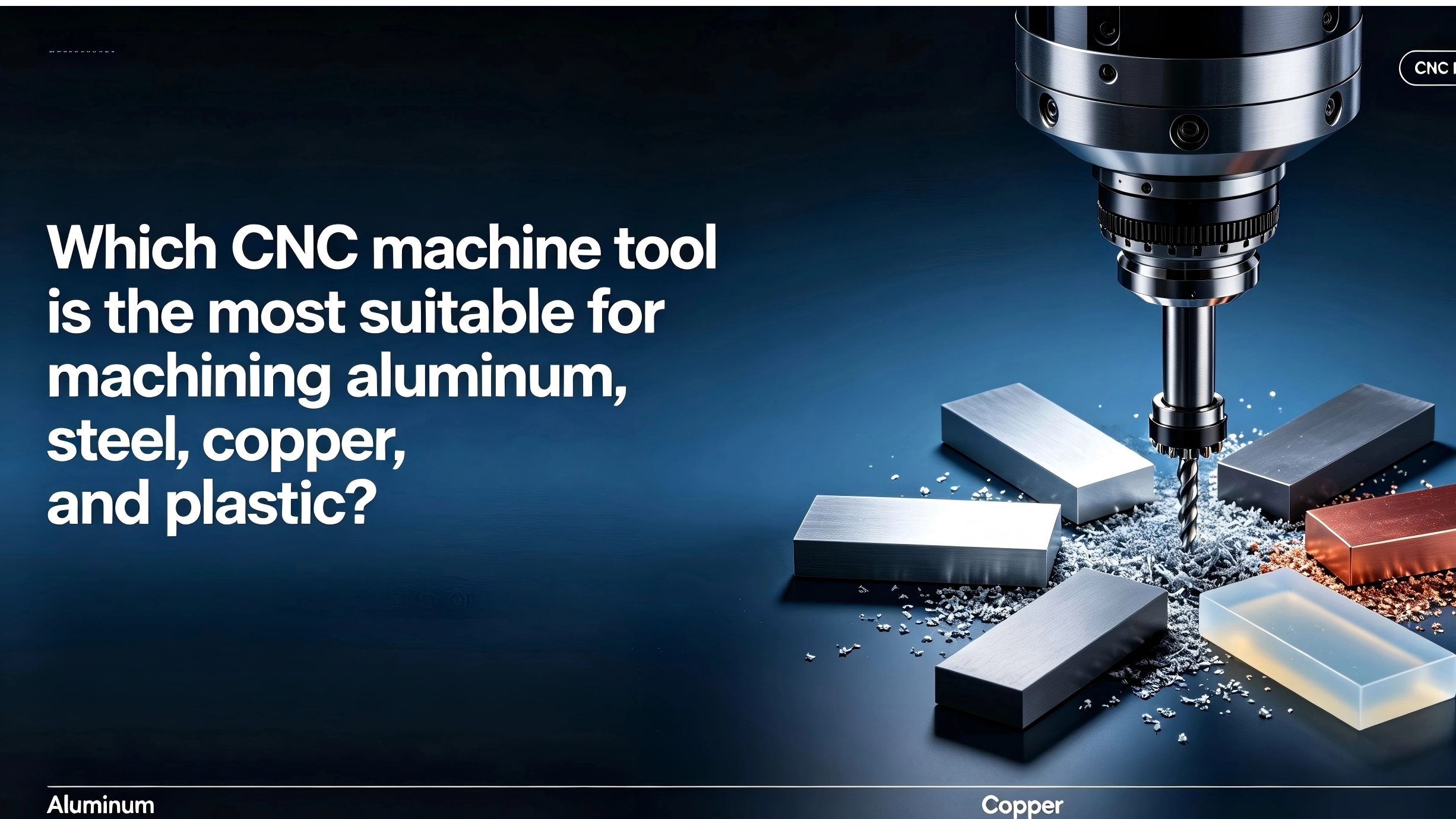 Understanding which machine tool is best suited for machining which material can assist machining factories and machine tool agents in making the optimal choice. This article introduces the materials that can be most effectively machined by CNC milling machines, CNC lathes, and CNC machining centers.CNC Machine Industry News
 -
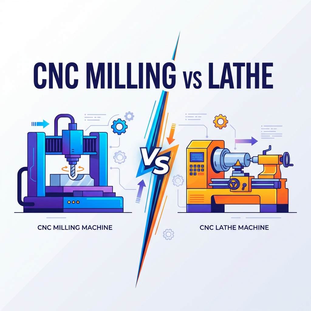 Compare CNC milling vs. turning. Learn differences in kinematics, geometry, cost, and automation to select the right machine for your production.Product news


