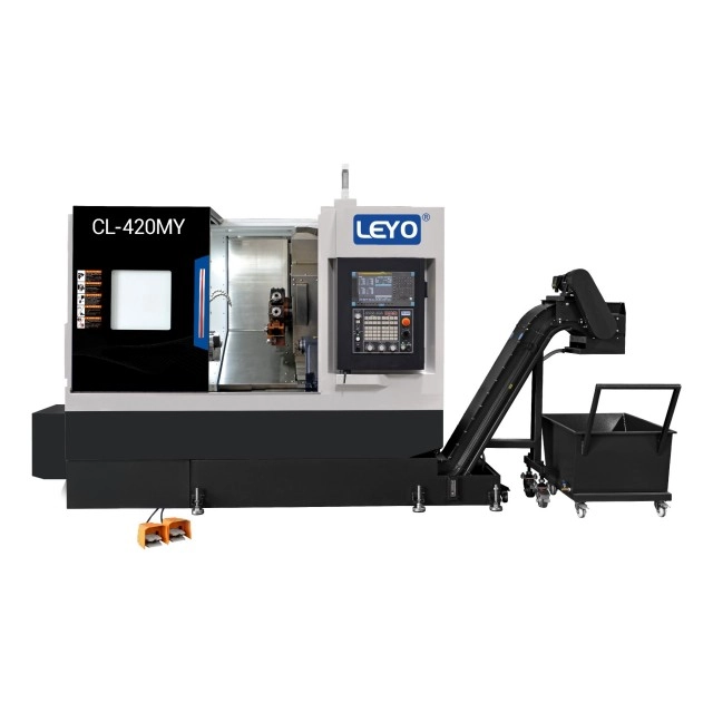

Transferring semi-finished components between dedicated lathes and milling machines introduces hidden manufacturing costs that rapidly erode profit margins. Inflated labor costs from manual refixturing, extended queue times between machine centers, and tolerance stacking caused by shifting datums create persistent production bottlenecks. Engineering and procurement teams constantly face the challenge of balancing the higher hourly rates of advanced multi-tasking machinery against tangible cycle time reductions, consolidated setups, and significant quality improvements. You need a strict evaluation framework to determine exactly which part geometries, tolerances, and production volumes justify routing to a combined CNC turning milling machine. Machining components in a single setup eliminates the runout introduced by secondary workholding. Understanding specific kinematic capabilities, tooling constraints, and break-even production volumes ensures optimal machine utilization and maximum return on investment.
Setup Reduction: Consolidating operations on a single machine eliminates tolerance stacking caused by multiple workholding setups, directly improving part accuracy.
Ideal Geometries: Parts with a primary revolved profile requiring secondary off-axis features (cross-holes, flats, keyways) yield the highest ROI.
Cost-to-Volume Ratio: The higher hourly cost of a turning milling center is offset by reduced labor and cycle times, particularly in medium-to-high volume production runs.
Design Constraints: Engineers must account for tool clearance, turret interference, internal fillet limitations, and sub-spindle handoff mechanics during the DFM phase.
The Strategic Role of the CNC Turning Milling Machine
Defining the Machine Architecture
Standard 2-axis lathes rotate a workpiece against a stationary cutting tool to create cylindrical profiles. Vertical or horizontal 3-axis mills rotate a cutting tool against a stationary workpiece to create prismatic features. Integrating these two distinct kinematic processes requires a robust mechanical foundation. A hybrid machine combines a high-torque main turning spindle with driven tool stations. This architecture allows a single machine platform to execute heavy roughing of outer diameters and precise contour milling without releasing the part from the chuck. We see this on the shop floor when a single bar-fed setup replaces three separate operations. You drop a raw slug in, and a finished part drops into the parts catcher. The massive cast-iron bed provides the dampening required to handle the interrupted cuts generated during milling operations on round stock. Without this rigidity, you get chatter, poor surface finish, and destroyed end mills.
Terminology Clarification: Live Tooling vs. Full Centers
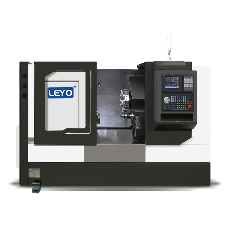
Distinguishing between machine classifications prevents routing inefficiencies. A basic live tooling CNC lathe typically utilizes a BMT or VDI style turret equipped with motorized tool holders. These machines handle simple radial or axial drilling, tapping, and basic slotting. They are excellent for putting a bolt hole circle on a flange. Conversely, a full turning milling center often features an independent B-axis milling head equipped with its own automatic tool changer (ATC). This articulating head allows for continuous multi-axis contouring, simultaneous 5-axis machining, and complex surfacing operations that a standard turret cannot physically execute. The ATC also solves the limited tool capacity problem of a standard 12-station turret, allowing you to load 40 or more tools for highly complex aerospace parts.
Machine Anatomy and Output Quality
The specific anatomy of the equipment dictates the complexity and tolerance limits of the machined components. The rigidity of the main spindle casting absorbs heavy turning vibrations, directly impacting surface finish. High-resolution glass scales ensure precise positioning during interpolated milling cuts. Furthermore, the processing speed of the CNC controller manages dense blocks of G-code. High-speed look-ahead capabilities prevent tool path hesitation during complex 3D milling routines, preventing dwell marks on the workpiece. When you push a 1-inch insert drill into 4140 steel, you need that mass to dampen the harmonics. The integration of thermal compensation sensors also plays a massive role. As the spindle heats up during a long production run, the machine automatically offsets the axes to maintain tight tolerances, ensuring the first part of the shift measures exactly the same as the last part.
Success Criteria and Problem Framing
Manufacturing goals drive the adoption of multi-tasking technology. The primary objectives include:
Achieving strict concentricity between turned inner/outer diameters and milled features.
Reducing total lead time by eliminating queue times between separate lathe and mill departments.
Minimizing operator intervention to reduce human error and enable lights-out manufacturing shifts.
Consolidating floor space by replacing multiple legacy machines with a single multi-tasking unit.
Ideal Part Profiles for a CNC Turn Mill (Solution Categories)
Primary Cylindrical Bodies with Secondary Milling
Parts whose main geometry consists of a revolved profile dominate this category. Drive shafts, alignment pins, mounting flanges, and fluid couplings require heavy turning operations to establish their primary dimensions. Specialized threaded fittings often require secondary features such as bolt-hole circles, milled flats for wrench clearance, or radial lubrication slots. Performing these secondary operations in one setup prevents runout issues. The machine maintains perfect alignment between the turned diameters and the milled features because the datum remains constant within the chuck jaws. If you unchuck a part to mill a hex on a separate machine, you instantly introduce a few tenths of runout. A CNC turn mill prevents this entirely. Consider a hydraulic spool valve. The outer diameter must be perfectly concentric with the internal milled metering notches. Doing this in two setups guarantees a rejected part. Doing it in one setup guarantees a perfect fit.
Complex Off-Center and Eccentric Features
Machining off-center features requires specific kinematics. A Y axis turning center provides true perpendicular movement across the spindle centerline. Without a physical Y-axis, machines rely on polar coordinate interpolation, which synchronizes X and C axis movements to simulate a flat cut. Polar interpolation often leaves poor surface finishes on flat walls and struggles with tight dimensional tolerances because the C-axis must constantly reverse direction at the centerline. True Y-axis movement machines custom camshafts, hydraulic manifolds, and eccentric crankpins with superior accuracy and surface finish. You get flat walls that actually measure flat with a dial indicator. The Y-axis also allows you to drill cross-holes that do not intersect the center of the part, a common requirement in manifold blocks and custom fasteners.
High-Precision Aerospace and Medical Components
Aerospace and medical sectors demand perfection from machined components. Titanium bone screws require complex thread forms and precise Torx drive heads. Dental implants need flawless micro-machining. Aerospace fluid fittings require perfect sealing surfaces to prevent catastrophic leaks under high pressure. Part-to-part consistency is mandatory in these highly regulated industries. Superior surface finish reduces friction and wear. Strict Geometric Dimensioning and Tolerancing (GD&T) compliance is non-negotiable, making a combined machining platform the only viable production method for these critical components. When machining 316L stainless steel or Grade 5 Titanium, the ability to apply high-pressure coolant directly through the tool in a rigid setup extends tool life and ensures excellent chip evacuation, preventing recutting and surface scoring.
Parts Requiring Back-End Machining (Done-in-One)
Sub-spindle integration defines the "done-in-one" manufacturing philosophy. The main spindle machines the front and outer features of the component. Once the primary operations conclude, the sub-spindle synchronizes its rotational speed, advances toward the main spindle, and grips the part. A parting tool then separates the component from the bar stock. The sub-spindle retracts and presents the back side of the part to the cutting tools. Manual refixturing is entirely eliminated. Concentricity between the front and back features remains absolute, and secondary operations disappear from the routing sheet. This is especially critical for parts with tight overall length tolerances or features on the back face that must align perfectly with features on the front face, such as timing gears or custom couplings.
Parts Better Suited for Alternative Machining Methods (Evaluation Dimensions)
Prismatic and Block-Like Components
Parts starting from square or rectangular billet belong on vertical or horizontal milling centers. Workholding dynamics favor vises, dovetail fixtures, or tombstone setups for block stock. A lathe chuck struggles to grip square stock securely at high RPMs, creating severe safety hazards and limiting spindle speeds. Furthermore, the material removal dynamics on 3-axis, 4-axis, or 5-axis mills are optimized for heavy roughing of block-like components. Turning square stock involves severe interrupted cuts that destroy lathe inserts and damage spindle bearings. If the part is 80% flat surfaces and pockets, put it on a mill. Trying to force a square peg into a round hole by machining a blocky part on a lathe is a recipe for broken tools and scrapped material.
Simple Rotational Geometries
Basic bushings, spacers, and standard threaded fittings lack milled features. These components require only turning, facing, and simple axial drilling. They should remain on standard 2-axis lathes. Routing simple parts to a high-end multi-tasking machine wastes advanced capabilities. The higher hourly burden rate of a multi-tasking machine quickly erodes profit margins on simple components. Keep high-end machines dedicated to high-margin, complex parts. If a part can be completed in 30 seconds on a basic chucker lathe, tying up a half-million-dollar multi-tasking center to run it is poor shop management. You want your advanced machines cutting complex contours, not turning simple washers.
Heavy Material Removal on Large Flats
Rigidity trade-offs dictate routing decisions. Heavy roughing of large flat surfaces requires massive spindle taper interfaces like CAT50, BT50, or HSK100. A power turret lathe utilizes smaller driven tool bearings and coupling mechanisms. Subjecting a live tool turret to extreme face milling loads causes severe chatter. Tool deflection increases exponentially. Dedicated rigid milling centers handle aggressive face milling and deep pocketing much better than any turret-based lathe. If the print calls for hogging out two inches of tool steel with a 3-inch face mill, you need a dedicated horizontal machining center. The live tooling gears in a lathe turret will simply strip out under that kind of radial load.
Cost and Volume Justification (Overall Value Influencing Factors)
Machine Hourly Rate vs. Total Cost Per Part
A direct financial comparison reveals the true value of multi-tasking equipment. A turning center with milling capabilities carries a significantly higher hourly burden rate than a standalone 2-axis lathe. However, evaluating the machine rate in isolation is flawed. You must calculate the combined rates of a separate lathe, a separate mill, and the associated operator handling time required to move the part between them. The consolidated process eliminates the secondary setup time, reduces scrap from refixturing errors, and ultimately drops the total cost per part.
To accurately calculate the break-even point, evaluate the following factors:
Calculate the total cycle time on the combined machine versus the combined cycle times of separate lathe and mill operations.
Quantify the labor cost of the operator tearing down and setting up the secondary milling operation.
Factor in the scrap rate reduction achieved by eliminating manual part transfer and datum shifts.
Assess the value of reduced queue times and faster order fulfillment.
Measure the cost of custom soft jaws and milling fixtures required for the secondary operations.
Production Volume Thresholds
Batch sizes heavily impact routing decisions. Mid-to-high volume production runs benefit immensely from the "done-in-one" approach. The cycle time savings and labor reductions compound over hundreds or thousands of parts. Conversely, low-volume prototyping might not always justify the effort. Complex CAM programming, tool touch-offs, and intricate setup procedures for dual spindles take hours. For a batch of three simple parts, routing them to separate manual or simple CNC machines might yield a faster overall turnaround time. However, if you are setting up a bar feeder to run 5,000 brass fittings over the weekend unattended, the multi-tasking machine is the only logical choice.
Work-in-Progress (WIP) Inventory Reduction
Reducing Work-in-Progress (WIP) inventory brings direct and measurable financial benefits. Outputting finished parts directly from one machine improves cash flow immediately. Semi-finished components no longer sit in bins waiting for a milling operation to become available. Floor space previously occupied by staging racks opens up for productive use. Production tracking becomes streamlined, as parts are either raw material or finished goods, with no ambiguous semi-finished states complicating the ERP system. When a part comes off the sub-spindle, it goes straight to inspection and then to shipping. You get paid faster, and you don't have capital tied up in half-finished metal sitting on the shop floor.
DFM and Implementation Risks (Risks & Mitigation)
Tool Clearance and Turret Interference
A crowded machining envelope presents severe physical constraints. Engineers must design parts to avoid collisions within the machine. Live tooling blocks protrude significantly from the turret face. Long boring bars swing dangerously close to the sheet metal enclosures during tool changes. The main chuck jaws, the advancing sub-spindle, and the workpiece share a confined space. Careful toolpath planning and rigorous design for manufacturability (DFM) reviews prevent catastrophic crashes. You have to model the exact chuck jaws and tool holder extensions in your CAM software. A half-inch miscalculation can result in a live tool block slamming into the sub-spindle at rapid traverse speeds, causing tens of thousands of dollars in damage.
Rigidity, Tool Deflection, and Internal Fillets
Live tooling rigidity has strict mechanical limits. Driven tools cannot match the stiffness of dedicated milling spindles. Engineers must limit the depth of milled pockets and avoid heavy interrupted cuts that shock the turret gear train. Design appropriate internal corner radii. Generous fillets allow the use of larger, stiffer end mills. This minimizes tool deflection, prevents premature tool breakage, and ensures the milled walls remain perfectly perpendicular to the turned surfaces. If a designer calls out a sharp internal corner at the bottom of a two-inch deep pocket, you will have to use a tiny end mill with massive stick-out. That tool will deflect, chatter, and snap. Change the design to allow a 0.250-inch radius, and you can use a half-inch end mill that plows through the material with zero issues.
Tooling Selection and Magazine Capacity Constraints
Turrets have a finite number of tool stations. A standard 12-station turret fills up rapidly when a part requires roughing, finishing, threading, grooving, and multiple driven milling tools. Recommend standardizing features during the design phase to conserve tool stations:
Use consistent tapped hole sizes across the entire part design to avoid loading three different tap sizes.
Keep thread pitches uniform wherever possible.
Standardize internal milled radii to minimize the number of unique end mills required.
Utilize multi-function tools like combination drill-chamfer mills to free up turret stations.
Employ quick-change tooling systems to swap worn inserts rapidly without losing offsets.
Programming and Operator Expertise
Implementation failure often stems from a lack of advanced CAM programming skills. Synchronizing dual spindles, managing part handoffs, and programming simultaneous multi-axis toolpaths requires complex G-code generation. Invest in robust simulation software. Digital twins verify toolpaths in a virtual environment. They detect gouges, limit overtravel, and prevent crashes before physical machining begins. Upgrading operator training is mandatory to handle the complexities of multi-tasking equipment. You cannot put a green operator on a twin-spindle Y-axis machine and expect success. They need to understand how to read the synchronized wait codes in the program and how to safely recover the machine if an alarm stops the cycle mid-handoff.
| Part Characteristic | Primary Geometry | Recommended Machining Platform | Primary Advantage |
|---|---|---|---|
| >70% Turned, requires off-axis milling | Cylindrical / Revolved | Turn-Mill Center / Power Turret Lathe | Eliminates secondary setups and maintains concentricity. |
| >80% Prismatic, heavy material removal | Square / Rectangular Block | 3-Axis, 4-Axis, or 5-Axis Mill | Maximum spindle rigidity for aggressive roughing. |
| 100% Turned, no milled features | Simple Cylindrical | Standard 2-Axis CNC Lathe | Lowest hourly burden rate for simple geometries. |
| Complex surfacing, off-center drilling | Eccentric / Revolved | Y-Axis Turning Center | True perpendicular milling without polar interpolation errors. |
Conclusion
Conduct a time-study comparison on your most frequently bottlenecked parts to identify setup reduction opportunities.
Submit a 3D CAD model of a complex component for a specific DFM and routing review.
Evaluate your current WIP inventory holding costs to quantify the financial impact of a "done-in-one" machining strategy.
Audit your CAM software capabilities to ensure it supports dual-spindle synchronization and kinematic simulation.
FAQ
Q: What is the difference between a CNC lathe and a CNC turning milling machine?
A: A standard CNC lathe only rotates the workpiece against stationary tools to create cylindrical parts. A turning milling machine adds rotating cutting tools, advanced controllers, and often Y or B axes. This allows the machine to perform complex milling, drilling, and tapping operations on a stationary or indexed turned part within the same setup.
Q: When should I use a Y axis turning center instead of a standard live tooling lathe?
A: A Y-axis is required for milling flat surfaces, cutting off-center keyways, or drilling holes that do not intersect the exact centerline of the part. Standard live tooling lathes rely on polar interpolation, which struggles with tight tolerances and leaves poor surface finishes on flat walls.
Q: Can a CNC turn mill completely replace a 5-axis milling machine?
A: No. Turn-mills are optimized for parts starting as round bar stock or cylindrical castings. 5-axis milling machines are generally required for prismatic block stock, heavy material removal, and large aerospace structural components where massive spindle rigidity is necessary for aggressive roughing.
Q: What materials are best suited for a power turret lathe?
A: Common materials include aluminum, stainless steel, titanium, brass, and alloy steels. Material choice directly affects live tool wear and deflection limits. Tougher materials like Inconel or titanium require reduced feeds and speeds to prevent overwhelming the driven tool bearings and causing chatter.
Q: How does a sub-spindle improve efficiency on a turning milling center?
A: A sub-spindle enables the "done-in-one" concept. It grabs the part from the main spindle, allows a parting tool to cut it off, and then finishes the back side of the component. This eliminates secondary manual setups, reduces operator handling time, and maintains strict concentricity between front and back features.
Related Articles
-
 Dear Customers and Business Partners,In order to strictly comply with national export control laws and regulations, and to fulfill international obligations, ensuring that our exported CNC milling machines and CNC lathes are fully legal and compliant, we hereby notify you of the relevant policies coCompany News
-
 Abrasive graphite dust destroys standard CNCs. Learn why specialized dust-proof machines and proper wet or dry milling methods are essential for safe EDM electrode production.Product news
-
 Drill tap centers deliver high-speed threading for high-volume production. Understanding spindle torque limits prevents costly tool breakage and optimizes machine cycle times.Product news