



In high-volume part production, non-cutting time drains profitability directly. Traditional tool changes accumulate hours of idle machine time per shift. Manufacturers relying on conventional CNC mills or manual drill presses face margin erosion. Slow chip-to-chip times, inconsistent thread quality, and bottlenecks in multi-feature part runs destroy throughput. Transitioning to a dedicated drilling tapping machining center equipped with a high-speed Automatic Tool Changer (ATC) shifts the production bottleneck. You convert idle transition seconds into active machining time. This guide evaluates the mechanics, productivity metrics, and implementation realities of rapid tool change systems. We will look at spindle dynamics, tooling requirements, and maintenance protocols that keep these machines running at peak efficiency.
Micro-efficiencies compound: Reducing tool change times to under two seconds dramatically lowers overall cycle times in high-volume, multi-hole applications.
Spindle dynamics matter as much as the ATC: True productivity relies on the synchronization of rapid tool changes with aggressive spindle acceleration/deceleration and high rapid traverse rates.
Rigidity vs. Speed trade-offs exist: While a high speed compact machining center excels at rapid transitions, buyers must evaluate thermal stability and tooling weight limits compared to heavier, traditional mills.
Maintenance dictates ROI: Sustaining rapid tool change speeds requires strict adherence to tooling tolerances, holder maintenance, and ATC alignment protocols to prevent catastrophic crashes.
The Mechanics of Rapid Tool Change in a Drilling Tapping Machining Center
Understanding how mechanical design dictates cycle time limits establishes baseline success criteria for machine evaluation. The architecture of the tool change system directly influences how quickly a machine moves from one operation to the next. You need to look past the marketing numbers and understand the physical movements happening inside the enclosure.
Automatic Tool Changer (ATC) Architecture
The design of the ATC mechanism is fundamental to achieving rapid cycle times in a compact drill tap center. Twin-arm mechanisms generally provide faster exchanges compared to umbrella or turret styles. They grip the current and next tool simultaneously. Servo-driven tool magazines ensure precise positioning and seamless tool exchange. This reduces mechanical shock during high-speed indexing.
Bidirectional, random-access tool selection minimizes rotational search delay during active machining. The magazine calculates the shortest path to the next required tool. It stages the tool while the spindle is still cutting. Cam-driven tool change mechanisms offer high reliability and mechanical synchronization. They ensure consistent speed metrics across thousands of cycles.
| ATC Type | Average Tool-to-Tool Time | Mechanism Reliability | Best Application |
|---|---|---|---|
| Turret Style | 1.5 - 2.0 seconds | High (fewer moving parts) | Simple, sequential hole making |
| Twin-Arm Servo | 0.8 - 1.2 seconds | Very High (cam driven) | Complex multi-tool operations |
| Umbrella Style | 3.0 - 5.0 seconds | Moderate | Older or entry-level mills |
Spindle Acceleration and Deceleration Dynamics
Chip-to-chip time provides a more accurate productivity metric than tool-to-tool time. It accounts for spindle deceleration, the physical tool swap, and spindle acceleration back to cutting speed. Low-inertia spindles are mandatory for rapid stopping and starting. This matters heavily during rigid tapping cycles where the spindle must reverse direction instantly at the bottom of the hole.
Synchronization of Z-axis retraction with ATC engagement eliminates idle air-cut time. The machine coordinates the spindle orientation and Z-axis movement. The tool is ready for extraction the exact moment it clears the workpiece. Heavy spindles take too long to spin down. A 30-taper spindle shines here because it lacks the mass of a 40-taper, allowing it to hit 10,000 RPM in milliseconds.
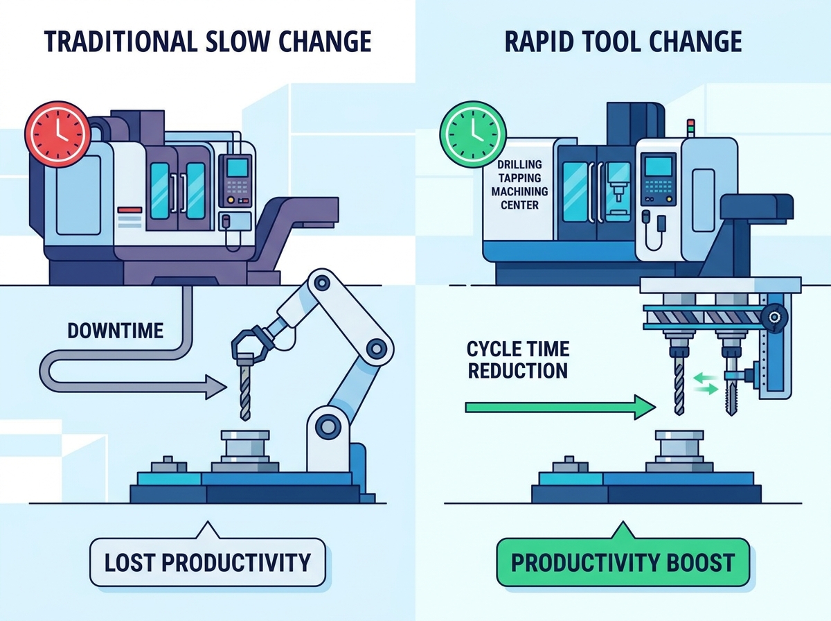
Quantifying Productivity: Cycle Time Reduction vs. Traditional Methods
Translating mechanical speed into measurable production metrics reveals the true value of rapid tool changes. Consistent performance and cost savings emerge when micro-efficiencies scale across high-volume production runs. We measure success by parts in the bin at the end of the shift.
Chip-to-Chip Time and High-Volume Runs
Calculating the cumulative time saved per shift based on a 1.5-second versus a 5-second tool change highlights significant productivity gains. In applications requiring hundreds of tool changes per hour, saving 3.5 seconds per swap yields hours of additional machining capacity each week. This directly impacts machine utilization rates and Overall Equipment Effectiveness (OEE).
Rapid, predictable cycles also maintain consistent drilling performance. Minimizing the time the tool spends out of the cut prevents tool cool-down and thermal shock. Keeping cutting conditions uniform extends tool life. When a carbide drill stays at a consistent operating temperature, the cutting edges resist micro-chipping.
| Metric | Standard VMC (40-Taper) | High-Speed Drill Tap Center | Time Saved Per 1000 Parts |
|---|---|---|---|
| Chip-to-Chip Time | 4.5 seconds | 1.5 seconds | 50 minutes |
| Spindle 0-10k RPM | 1.8 seconds | 0.4 seconds | 23 minutes |
| Z-Axis Retract | 1.2 seconds | 0.5 seconds | 11 minutes |
Simultaneous Operations and Multi-Feature Machining
Consolidating drilling, chamfering, and tapping into a single automated setup eliminates work-in-progress inventory. It stops manual part handling. Comparing the cycle times of a dedicated machine against sequential routing through manual drill presses demonstrates massive throughput improvements.
Evaluating CNC rigid tapping capabilities against traditional drill presses equipped with mechanical tapping attachments reveals superior speed and depth control. Rigid tapping synchronizes feed and speed precisely. It eliminates the need for tension-compression holders. You get faster, more accurate thread creation without the mechanical lag of a tapping head.
Core Evaluation Dimensions for a High Speed Compact Machining Center
Assessing machine capabilities against specific production requirements requires analyzing industry-standard evaluation dimensions. Tool capacity, spindle torque, and axis positioning speeds must align with your intended applications. You cannot buy a machine based on rapid traverse alone.
Tool Capacity and Magazine Design
Determining optimal tool capacity depends on part complexity and tool redundancy requirements. A 14-tool magazine might suffice for simple parts. A 21-tool capacity allows for redundant tooling in lights-out manufacturing scenarios. Buyers must evaluate the impact of magazine weight on machine vibration and tool change speed. Heavier magazines increase inertia and slow down indexing.
When you load a 21-tool magazine with heavy steel holders, the servo must work harder to index the carousel. This can introduce milliseconds of delay. For ultra-high-speed operations, operators often balance the magazine load, placing heavier tools opposite each other to maintain rotational stability.
High-Torque Capabilities for Rigid Tapping
Assessing spindle torque curves is necessary for tapping harder alloys like titanium, stainless steel, or cobalt-chrome. You need torque without sacrificing rapid traverse or tool change velocity. High-torque configurations in precision sectors meet the strict quality and throughput demands of medical manufacturing.
The necessity of synchronized feed and spindle rotation ensures properly formed threads and maximizes tap longevity. Without precise synchronization, the tap drags or binds. This leads to poor thread quality or tool breakage. A high speed compact machining center uses high-resolution encoders to lock the Z-axis feed to the spindle rotation perfectly.
Rapid Traverse Rates and Axis Positioning
Evaluating X, Y, and Z-axis rapid traverse rates provides a complete picture of non-cutting time. These rates often exceed 48m/min. Linear guideways play a massive role in maintaining positioning accuracy during these high-speed transitions. They ensure the machine settles quickly and accurately before the cut begins.
Box ways are too slow for this type of work. Roller linear guideways offer the best combination of speed and rigidity. They handle the aggressive acceleration and deceleration forces generated when the machine moves from hole to hole in fractions of a second.
Operational Trade-Offs: Speed vs. Rigidity in a Compact Drill Tap Center
Prioritizing rapid tool change involves conceptual trade-offs. Buyers must accept certain limitations regarding rigidity and work envelope to achieve maximum speed. You cannot have a machine that roughs inconel like a 50-taper horizontal and taps aluminum like a 30-taper drill mate.
Footprint vs. Work Envelope
Maximizing floor space ROI is a primary advantage of the compact footprint. These machines pack high productivity into a minimal area. You can often fit two drill tap centers in the space of one standard vertical mill. However, this compact design imposes limitations on part size and fixture complexity due to restricted X and Y-axis travel.
You must plan your fixturing carefully. Large trunnion rotary tables might not fit. You will likely rely on dense grid plates or custom pneumatic vises to maximize the number of parts you can fit inside the smaller work envelope.
Thermal Stability During High-Speed Operations
Managing heat generation from continuous rapid tool changes and high-speed spindle cycles is mandatory for maintaining part accuracy. Evaluating thermal compensation software and coolant-through-spindle (CTS) options helps maintain tight tolerances during extended runs. Heat causes the casting to grow, shifting your Z-axis zero point.
Weight limitations on tooling must also be considered. Heavy boring bars or large-diameter cutters impact ATC speed. They accelerate spindle wear on lighter 30-taper machines. These spindles are optimized for speed rather than heavy material removal. Stick to the manufacturer's recommended tool weight limits to avoid dropping tools during a change.
Implementation Realities and Adoption Risks
Adopting high-speed machining technology requires addressing evidence-oriented realities. Tooling compatibility, operator training, and maintenance protocols are essential for sustained success. You cannot run these machines using the same sloppy practices you might get away with on a slow toolroom mill.
Tooling Compatibility and Holder Requirements
High-speed operations necessitate balanced tool holders. BT30 or BBT30 dual-contact interfaces minimize runout and vibration. Integrating quick-change tooling solutions reduces offline measurement, validation, and setup times. Proper tooling selection mitigates the risk of tool pull-out during aggressive spindle deceleration.
Inspect all tool holder tapers for fretting or galling before loading them into the magazine.
Verify that the pull studs match the exact specification required by the machine's drawbar.
Balance all tool assemblies to G2.5 at the maximum operating RPM of the spindle.
Clean the spindle taper daily with a dedicated taper wiper to remove coolant residue and chips.
Operator Training and Setup Protocols
Accurate tool length measurement and offset management prevent ATC crashes at high speeds. Operators must adapt CAM programming to optimize tool paths. You need to minimize unnecessary tool changes and pre-stage tools in the magazine to fully leverage the machine's capabilities.
If your CAM software outputs a tool change command, but the next tool is on the opposite side of the carousel, you lose time. Programmers should sequence operations so the magazine only needs to index one or two pockets between changes.
Mitigating Wear on ATC Mechanisms
Establishing preventative maintenance schedules for cam followers, gripper fingers, and ATC alignment ensures long-term reliability. Regularly monitoring the pneumatic or hydraulic systems that actuate the tool release mechanism prevents tool drops and costly downtime.
Check the ATC alignment pin weekly to ensure the arm is perfectly concentric with the spindle centerline.
Grease the cam mechanism according to the manufacturer's specified intervals using the exact recommended lubricant.
Inspect the gripper finger springs for fatigue. Replace them annually regardless of visual condition.
Verify drawbar clamping force using a pull-stud dynamometer every six months.
Conclusion
Conduct a time-study analysis on your most frequently run multi-hole parts to quantify potential cycle time savings.
Request a test cut from manufacturers to verify chip-to-chip times and thread quality under real-world conditions.
Audit your current tooling inventory to ensure compatibility with high-speed 30-taper spindles and dual-contact requirements.
Establish a strict preventative maintenance schedule for tool holders and ATC mechanisms before initiating procurement.
FAQ
Q: What is the average tool change time for a drilling tapping machining center?
A: Modern centers typically achieve tool-to-tool times of 0.8 to 1.5 seconds, and chip-to-chip times between 1.5 and 2.5 seconds. This depends heavily on the ATC design, the weight of the tools in the magazine, and the acceleration capabilities of the spindle motor.
Q: How does a compact drill tap center differ from a standard vertical machining center (VMC)?
A: A compact drill tap center utilizes a lighter, lower-inertia spindle, usually a 30-taper. It features a specialized ATC designed to prioritize rapid acceleration, deceleration, and tool changes over the heavy milling and roughing capabilities found on a standard 40-taper or 50-taper VMC.
Q: Can a high speed compact machining center handle heavy milling?
A: While capable of light to medium milling, these machines are optimized for axial operations like drilling and tapping. Heavy radial cuts can cause severe vibration and premature spindle bearing wear due to the lighter 30-taper interface and lower overall machine mass.
Q: What is rigid tapping, and why is it important?
A: Rigid tapping synchronizes the machine's spindle rotation with the Z-axis feed rate perfectly. This allows for precise thread creation without the need for tension-compression tapping heads. It speeds up the cycle time and improves thread depth accuracy significantly.
Q: How do I prevent tool drops during rapid tool changes?
A: Preventing tool drops requires using high-quality, properly maintained tool holders. You must ensure the machine's drawbar pressure is within factory specifications. Routinely inspect the ATC gripper fingers and springs for wear, and never exceed the maximum tool weight limit.
Q: Does a faster ATC increase tool wear?
A: The ATC speed itself does not increase cutting tool wear. However, the aggressive spindle acceleration and high-speed machining parameters associated with these centers require high-quality carbide tooling and optimized coolant delivery to prevent premature edge wear and thermal shock.
Related Articles
-
 Dear Customers and Business Partners,In order to strictly comply with national export control laws and regulations, and to fulfill international obligations, ensuring that our exported CNC milling machines and CNC lathes are fully legal and compliant, we hereby notify you of the relevant policies coCompany News
 -
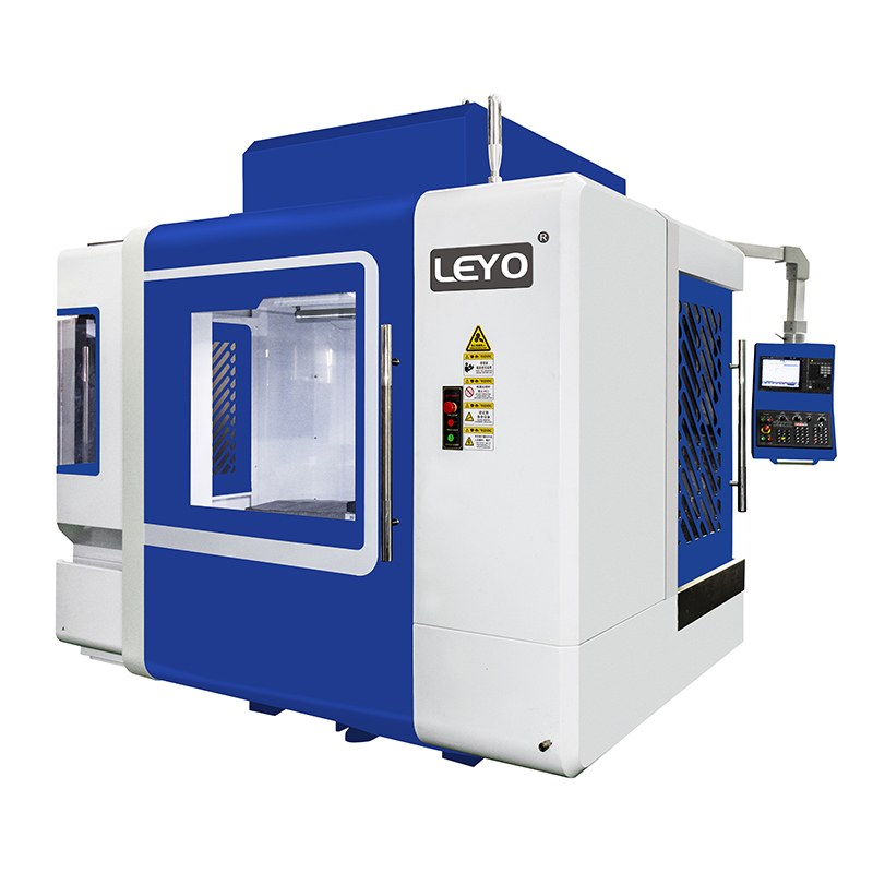 Eliminate part deflection and chatter. Master expert workholding strategies for vertical milling machines to maximize CNC precision and reduce scrap.Product news
 -
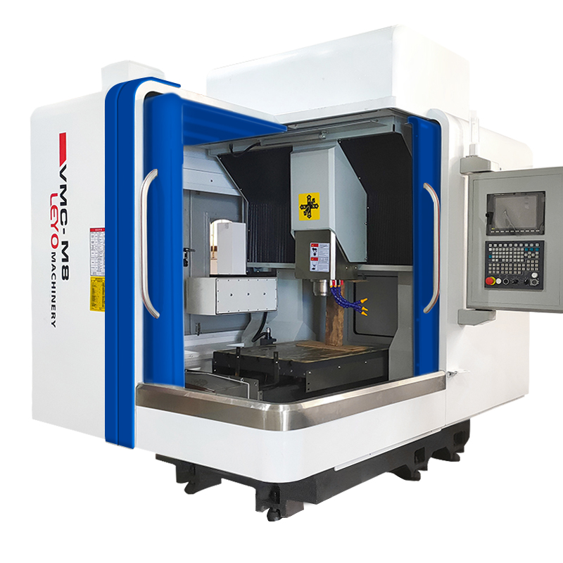 Stop tool breakage and scrap parts. Discover how horizontal milling machines use gravity for flawless chip evacuation and maximum ROI.Product news


