



Mold production leaves zero room for error. When you machine complex 3D geometries, deep cavities, and intricate cores, micron-level deviations or poor surface finishes instantly scrap expensive tool steel. This reality forces mold makers to balance aggressive material removal during roughing with the extreme precision required for final finishing passes. You need equipment that handles heavy chip loads without compromising the final dimensional accuracy of the mold cavity.
While various machining centers handle general metalworking, the vertical milling machine remains the foundational asset for mold shops. Its mechanical layout provides distinct advantages for cavity work, allowing gravity to assist with workpiece seating and chip management in specific setups. This guide provides a technical evaluation framework for selecting equipment that meets strict mold-making tolerances and heavy production demands, ensuring your shop floor operates efficiently.
Spindle Orientation Dictates Capability: The vertical spindle alignment is uniquely suited for the plunge cutting, drilling, and intricate detail work required in mold cavities.
Rigidity is Non-Negotiable: Successful mold machining in hardened tool steels requires a machine base and column designed for maximum vibration dampening and thermal stability.
Control Systems Drive Surface Finish: A high-end precision vertical milling center relies on advanced processing speeds and look-ahead capabilities to execute complex CAD/CAM toolpaths without gouging or stuttering.
Automation Bridges the Gap: Integrating spindle probes and magnetic pallet tables transforms a standalone vertical mill for mold machining into a scalable, high-efficiency production cell.
The Strategic Role of the Vertical Milling Machine in Mold Making
Successful mold production relies on strict baseline requirements. Dimensional accuracy must remain consistent across large, heavy workpieces. The machine must deliver a superior surface finish to reduce manual polishing time, which often bottlenecks mold delivery. Furthermore, the equipment must efficiently machine hardened alloys like P20, H13, and S7 tool steels. Meeting these criteria requires a machine built specifically for rigidity and precision, not just general-purpose cutting.
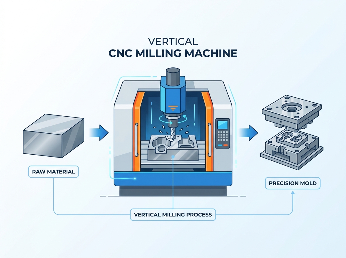
The mechanical dynamics of a vertical setup directly support these shop floor goals. The cutting tool rotates within a vertically-oriented spindle moving along the Z-axis. Controlled machine motion guides the table and workpiece along the X and Y axes. This vertical orientation allows gravity to assist in seating the workpiece flat against the table or fixture. It provides operators with a clear, unobstructed line of sight during complex setups, indicating exactly where the tool engages the block.
A vertically oriented spindle excels at specific toolpath strategies used daily in mold shops. Plunging operations benefit from the direct downward force applied along the Z-axis. Intricate pocketing required for deep mold cavities and cores is easier to program and execute when the tool approaches from above. The machine transitions across the entire mold lifecycle seamlessly.
Operators square up raw blocks and rough out excess material using high-feed mills.
The machine executes semi-finishing passes to step down the geometry and leave a uniform stock allowance.
Final high-speed finishing passes utilize small-diameter ball end mills to generate the final cavity shape.
Drilling and tapping cycles finish the ejector pin holes and cooling channels.
When you evaluate a machine for these tasks, you must look beyond the basic specifications. The ability to hold a tight tolerance while roughing out a block of P20 steel dictates the true value of the equipment. If the machine frame flexes during heavy cuts, you will spend hours benching and polishing the final mold to fix the dimensional errors.
Core Anatomy: What Makes a Vertical Mill for Mold Machining Effective?
Spindle Dynamics: Speed vs. Torque
Selecting the right spindle involves a direct trade-off between torque and speed. High-torque spindles are necessary for roughing tough materials. They provide the sheer cutting force needed to push large face mills and high-feed cutters through hardened steel quickly. A geared head or a high-torque inline direct drive spindle provides the low-end grunt required to remove large volumes of material without stalling.
Conversely, high-speed spindles operating at 15,000 to 30,000 RPM are required for finishing passes. These high speeds allow small-diameter tools to achieve optimal surface footage and chip loads without breaking. When you use a 1/16-inch ball mill to finish a tight corner, you need RPM to maintain the cutting action. Without sufficient speed, the tool rubs against the material, generating heat, deflecting, and eventually snapping.
Spindle taper options heavily impact tool rigidity and runout at high speeds. A standard CAT40 taper offers excellent gripping force for general mold work and heavy roughing. However, HSK-A63 tapers provide superior dual-contact seating. This dual-contact design minimizes tool deflection and maintains strict concentricity during high-speed finishing operations, preventing chatter marks on the mold surface.
| Spindle Taper | Primary Advantage | Best Mold Application | High-Speed Performance |
|---|---|---|---|
| CAT40 | High gripping force, widespread availability | Heavy roughing, large face milling | Moderate (Prone to bell-mouthing at extreme RPM) |
| HSK-A63 | Dual-contact seating, high rigidity | High-speed finishing, 3D contouring | Excellent (Maintains concentricity at 20k+ RPM) |
| BBT40 (Dual Contact) | Combines CAT40 tooling with face contact | Mixed roughing and finishing | Very Good |
Structural Rigidity: The Base and Column Foundation
The machine base provides the foundational stability required for mold making. It must damp heavy vibrations generated when milling hardened tool steels. A massive, well-ribbed base absorbs these frequencies, preventing chatter marks on the mold surface. If the base lacks mass, the vibration transfers directly into the cutting tool, destroying the surface finish and reducing tool life.
The column design is equally critical. A robust column rigidly supports the spindle head. It must resist severe bending moments during high-feed Z-axis plunging operations. When a high-feed mill enters the cut, it pushes back against the spindle. A weak column will bow backward, causing the tool to cut shallow and leaving excess material on the workpiece.
Material selection for the machine frame dictates its dampening capabilities. Cast iron remains the industry standard, offering excellent vibration absorption and structural rigidity. Meehanite cast iron, in particular, provides a dense, uniform grain structure ideal for machine tools. Some advanced machines utilize polymer concrete construction. Polymer concrete provides even greater vibration dampening and superior thermal stability compared to traditional cast iron, making it highly desirable for ultra-precision mold work.
Axis Configuration and Guideways
Guideway selection determines how the machine handles cutting forces and rapid movements. Linear guideways offer faster rapid traverse rates and lower friction. They utilize recirculating ball bearings or roller bearings on a profiled rail. Roller linear guides provide a great balance of speed and rigidity, making them highly effective for light, high-speed finishing passes where the machine must change direction rapidly.
Box ways provide superior rigidity and vibration damping. They consist of solid cast iron ways that slide against each other, separated by a thin film of oil (Turcite). They offer a massive surface contact area, making them ideal for heavy roughing in hard metals. However, box ways suffer from stick-slip at very low feed rates, which can negatively impact surface finish during slow, precise contouring.
Axis travel capacities must align with the shop's production goals. The X, Y, and Z travels must accommodate the maximum mold base size the shop intends to produce, plus clearance for tooling and workholding. Insufficient Z-axis travel severely limits the ability to machine deep cavities, use long tool holders, or integrate rotary tables for multi-sided machining.
Evaluating a Precision Vertical Milling Center
CNC Control Systems and Processing Power
Mold making requires advanced CNC controls capable of handling massive code files generated by modern CAM software. A precision vertical milling center relies on high block-processing speeds. Advanced look-ahead algorithms read thousands of lines of code ahead of the actual cut. This processing power prevents the machine from stuttering during complex 3D contouring.
When a machine stutters, the tool dwells on the material for a fraction of a second. This dwell causes the tool to rub, generating heat and leaving a visible gouge or faceted mark on the surface. High-speed look-ahead ensures smooth, continuous axis motion by calculating the optimal acceleration and deceleration curves for the programmed geometry. This smooth motion translates directly into mirror-like surface finishes, drastically reducing the need for manual polishing.
You must verify the control's data processing capabilities. Look for controls that offer specific high-speed machining (HSM) modes. These modes allow the operator to adjust the machine's behavior, prioritizing either strict dimensional accuracy or smoother, faster motion depending on the specific operation being performed.
Thermal Stability and Compensation
Thermal expansion is a harsh reality during long finishing cycles. Mold finishing programs often run unattended for 10 to 20 hours. Heat generated by the spindle bearings, ballscrew friction, and ambient shop temperature fluctuations causes the machine frame to expand and contract. This thermal drift ruins tight tolerances, causing mismatch lines where different tools blend together.
Mitigating this risk requires dedicated hardware and software. Spindle chillers circulate temperature-controlled fluid around the spindle cartridge to maintain a constant operating temperature. Hollow ballscrews with internal cooling prevent axis growth during rapid, repetitive movements. Without ballscrew cooling, the friction heats the screw, causing it to lengthen and introducing positioning errors.
Real-time thermal compensation software uses sensors placed strategically across the machine casting. The control monitors these temperatures and uses algorithms to predict and adjust for thermal drift dynamically. It applies micro-offsets to the axes, ensuring the tool tip remains exactly where the program dictates, regardless of how much the machine casting has expanded.
Workholding and In-Process Automation
Standardized workholding transforms machine utilization rates. Magnetic pallet tables and zero-point clamping systems enable "zero-engineering" setups. Operators prep raw material on a pallet outside the machine while the spindle is cutting another part. Once the previous job finishes, the new pallet locks into place instantly with repeatable micron-level accuracy. This drastically reduces downtime between setups.
In-process inspection further enhances productivity and quality control. Integrating spindle probes allows for automated part alignment. The probe locates the workpiece, updates work offsets automatically, and verifies critical dimensions before the part leaves the machine. This automation reduces setup times, eliminates costly human alignment errors, and allows for unattended machining with confidence.
Tool setting probes are equally important. Laser tool setters measure tool length and diameter at operating RPM, accounting for spindle growth and tool runout. They also detect broken tools automatically, stopping the machine before a broken cutter ruins the workpiece or causes a collision.
Vertical vs. Horizontal Milling: Trade-offs in Mold Production
When to Choose Vertical
A vertical mill for mold machining requires a lower initial capital investment compared to horizontal alternatives. It also occupies a significantly smaller floor space footprint. This makes it highly attractive for independent mold shops maximizing their facility layout and capital expenditure budgets.
The vertical layout demonstrates clear superiority in specific applications. Detailed plunge work benefits from the vertical Z-axis orientation, allowing the thrust forces to direct straight down into the rigid machine table. Drilling deep ejector pin holes is straightforward and highly accurate. Machining flat, plate-like mold components is inherently easier when gravity holds the plate flat against the table, simplifying workholding requirements.
Operators generally find vertical machines easier to set up and monitor. The open front access allows for easy loading of heavy mold bases using an overhead crane. The operator can stand directly in front of the machine and visually verify the tool path and coolant flow, which is critical during first-article prove-outs.
Managing the Chip Evacuation Challenge
Vertical milling has one primary weakness in deep cavity work. Gravity traps chips at the bottom of the pocket. If chips are not evacuated immediately, the cutter recuts them. This leads to poor surface finish, accelerated tool wear, and catastrophic tool breakage. Recutting work-hardened chips will destroy a carbide end mill in seconds.
Mitigating this challenge requires specific machine features and programming strategies. High-pressure through-spindle coolant (TSC) blasts chips out of deep pockets, providing lubrication and clearing the cutting zone simultaneously. Programmable air blasts clear chips when cutting dry, which is often required to avoid thermal shock on coated carbide tools during hard milling.
Specialized CAM tool path strategies also help manage chip loads in deep cavities. Ramping and helical entry methods reduce the initial shock on the tool. Peck drilling cycles break chips into manageable sizes. Air-blow systems integrated into the spindle face provide a continuous stream of air to keep the cutting zone clear when TSC is not applicable.
Implementation Risks and Mitigation Strategies
Tool Deflection and Surface Finish Failures
Using long-reach tooling for deep mold cavities introduces significant risk. Long tools lack rigidity. This leads to chatter, poor surface finish, and severe dimensional inaccuracy. The tool deflects away from the cut, leaving excess material on the mold walls. When the tool deflects, it also changes the effective cutting geometry, leading to unpredictable tool wear.
Mitigation requires a multi-faceted approach. Specify machines with high dynamic stiffness to resist vibration. Adopt shrink-fit tool holders for maximum gripping force and minimal runout. Shrink-fit holders provide a symmetrical profile that maintains balance at high RPMs. Utilize CAM software to generate constant-engagement toolpaths.
Trochoidal milling strategies keep the tool load consistent, reducing deflection even with long-reach tools. By taking light radial step-overs at high feed rates, the tool avoids burying itself in the corners, maintaining a constant chip thickness and preventing catastrophic failure.
CAD/CAM Integration Bottlenecks
A high-performance vertical CNC milling machine is easily bottlenecked by outdated software. Poor post-processors fail to utilize the machine's full capabilities. If the CAM system cannot output high-speed surfacing code, or if the post-processor outputs point-to-point data instead of smooth arcs, the machine's advanced hardware sits idle.
Ensure the new machine control is fully compatible with the shop's existing CAD/CAM ecosystem. Budget specifically for custom post-processor development during the purchase phase. A good post-processor will automatically output the correct HSM codes, coolant commands, and probe cycles.
Invest in operator training to ensure programmers understand how to leverage advanced look-ahead and high-speed machining cycles. A machine is only as capable as the code driving it. Training ensures your team can extract the maximum return on investment from the new equipment.
Conclusion
Audit your current mold sizes and material hardness to determine the exact spindle torque and axis travel requirements before contacting vendors.
Require machine tool builders to perform test cuts on your specific tool steel grades to verify their claims regarding surface finish and volumetric removal rates.
Implement shrink-fit tooling and zero-point clamping systems immediately upon machine installation to maximize spindle uptime and reduce setup bottlenecks.
Schedule dedicated CAM software training for your programmers to ensure they can generate the high-speed, constant-engagement toolpaths required for modern mold machining.
FAQ
Q: What is the difference between a standard vertical mill and a precision vertical milling center?
A: A precision center is built specifically for tight tolerances. It features enhanced structural rigidity, often utilizing heavier castings or polymer concrete. It includes active thermal compensation to manage heat growth. Furthermore, it utilizes advanced CNC processing power with high-speed look-ahead to handle complex 3D surfacing without stuttering.
Q: Why is spindle speed critical in a vertical mill for mold machining?
A: High spindle speeds are required for finishing passes. Mold finishing relies on small-diameter tools to reach into tight corners and intricate details. To achieve the correct surface speed and chip load without breaking these small tools, the spindle must rotate at very high RPMs, often exceeding 15,000 RPM.
Q: How does a vertical CNC milling machine handle deep cavity machining?
A: Deep cavity machining presents chip evacuation challenges due to gravity. The machine handles this by utilizing high-pressure through-spindle coolant (TSC) or programmable air blasts to force chips out of the pocket. Operators also use specialized toolpaths to manage engagement and prevent chip recutting.
Q: Can a vertical milling machine cut hardened tool steel?
A: Yes. Cutting hardened tool steel requires a rigid machine setup. Success depends on heavy box ways or oversized linear guides, a high-torque spindle for roughing, and a massive base to absorb vibration. Using appropriate coated carbide tooling and rigid tool holders is also mandatory.
Q: What role does thermal compensation play in mold making?
A: Mold finishing cycles often run for many hours. During this time, heat from the spindle and motors causes the machine casting and ballscrews to expand. Thermal compensation uses sensors and software to adjust axis positions dynamically, ensuring micron-level accuracy is maintained throughout the long cycle.
Q: How do I choose between a 3-axis and a 5-axis vertical milling machine for molds?
A: A 3-axis machine is simpler, costs less, and handles most standard mold plates and straightforward cavities. A 5-axis machine is necessary for highly complex molds. It allows for shorter tool reach by tilting the workpiece, which reduces tool deflection, improves surface finish, and eliminates multiple manual setups.
Related Articles
-
 Dear Customers and Business Partners,In order to strictly comply with national export control laws and regulations, and to fulfill international obligations, ensuring that our exported CNC milling machines and CNC lathes are fully legal and compliant, we hereby notify you of the relevant policies coCompany News
 -
 Eliminate part deflection and chatter. Master expert workholding strategies for vertical milling machines to maximize CNC precision and reduce scrap.Product news
 -
 Stop tool breakage and scrap parts. Discover how horizontal milling machines use gravity for flawless chip evacuation and maximum ROI.Product news


