



Traditional machining hides massive operational costs in plain sight. Spindles sit idle while operators manually unclamp, clean, flip, and re-indicate parts. This constant handling introduces a compounding risk of human error during multiple setups. Every time a part leaves the vise, you lose your original reference point. Three-axis and four-axis limitations on complex multi-sided geometries force shops into extensive fixturing. This creates severe tolerance stacking, increases scrap rates, and drastically inflates labor costs. You need an architectural shift on the shop floor. Implementing a 5 axis machining center achieves "done-in-one" production. This technology shifts the manufacturing bottleneck away from manual setup. It puts the focus directly back on actual cutting time, allowing shops to machine complex geometries without constantly breaking down setups.
Elimination of Tolerance Stacking: Machining five sides of a part in a single clamping inherently removes the compounding dimensional errors caused by manual repositioning.
Spindle Utilization Increases: Drastically reducing non-productive time (NPT) spent on setup and teardown directly correlates to higher overall equipment effectiveness (OEE) and faster part throughput.
Configuration Flexibility: Solutions range from a compact 5 axis machining center for high-mix/low-volume medical parts to a five axis gantry machining center for massive aerospace components.
Implementation Realities: Realizing these efficiency gains requires prerequisite investments in advanced CAM software, robust post-processors, and specialized zero-point workholding.
The Mechanics of Repositioning Waste in Traditional Machining
Tolerance Stacking Across Multiple Setups
Tolerance stacking represents a harsh mathematical reality in precision manufacturing. Every unclamping and reclamping sequence introduces a new datum shift. When an operator moves a part from operation one to operation two, the original X, Y, and Z coordinates disappear. The machine must rely on newly probed surfaces to establish a secondary datum. Even a perfect vise setup introduces microscopic deviations. A tiny chip under a parallel or a slight variation in clamping pressure causes the part to lift or tilt. These errors might measure just a few tenths of a thousandth of an inch initially.
These micro-deviations compound rapidly across three to six operations. An angular error on the second setup multiplies the linear error on the third setup. This stacking effect often pushes tight-tolerance parts completely out of spec by the final operation. Parallelism and perpendicularity suffer the most. You cannot hold true position across opposing faces when you manually flip the workpiece. Contrast this with a single-setup baseline. When you machine the entire part in one clamping, the machine's volumetric accuracy dictates the final part tolerance. The spindle maintains a constant mathematical relationship with the workpiece from the first cut to the last.
The Hidden Costs of Fixturing and Operator Intervention
Traditional multi-setup machining drains engineering resources. Programmers and manufacturing engineers waste countless hours designing custom soft jaws. They build complex aluminum or steel fixtures just to hold parts for secondary and tertiary operations. These fixtures require their own machining time, materials, and storage space. Every new part revision forces the shop to modify or scrap these custom workholding solutions. This constant fixture creation acts as a massive hidden tax on overall profitability.
Operator intervention carries a steep labor cost. Traditional alignments require intense manual complexity. Operators spend valuable time tilting axes and moving the Z-axis to clear clamps. They repeat manual edge-finding procedures for every single new setup. Dialing in a part with a test indicator takes time and high skill. This physical labor inflates non-productive time. Spindles stop turning while operators wrestle with wrenches and indicators. This bottleneck directly impacts shop scheduling. Parts sit in work-in-progress queues waiting for the next available machine or setup. Lead times stretch from days into weeks simply because the parts spend more time waiting in bins than they do being cut.
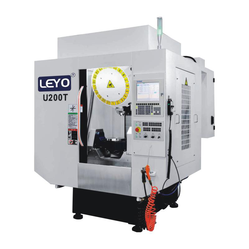
How a 5 Axis Machining Center Achieves "Done-in-One" Production
Single-Datum Alignment and Automated Probing
Establishing a single datum via on-machine probing transforms the machining workflow. A spindle-mounted probe touches off the raw stock once. It establishes the absolute X, Y, and Z zero points for the entire manufacturing cycle. You completely eliminate the need for repetitive manual edge-finding across multiple operations. The machine knows exactly where the part sits in three-dimensional space. The rotary and tilt axes adjust automatically to present different faces to the spindle.
The standard automated probing sequence follows these exact steps:
Load the raw stock into the self-centering vise or dovetail fixture.
Call the spindle probe to establish the primary Z-axis height on the top face of the material.
Probe the X and Y extents to find the exact center of the raw block.
Write these coordinates to the machine's active work offset.
Activate the machine's dynamic tracking to lock this datum to the center of rotation.
Locking in the workpiece coordinates once ensures perfect alignment between features on all five accessible sides. If a hole on the top face must intersect perfectly with a cross-hole on the side face, the machine executes this flawlessly. The single datum eliminates the risk of human error during part transfer. Operators no longer need to worry about seating the part perfectly against a vise stop. The machine's kinematic model handles the spatial math, ensuring that every drilled hole, milled pocket, and tapped thread maintains strict geometric tolerance to the original reference point.
Continuous 5-Axis vs. 3+2 Positional Machining
Understanding the difference between 3+2 positional machining and simultaneous 5-axis contouring dictates your programming strategy. In 3+2 machining, the machine positions the cutting tool at a fixed angle using the A and B or C axes. It then locks those rotary axes firmly into place using mechanical or hydraulic brakes. The actual cutting happens using standard 3-axis milling moves. Simultaneous 5-axis contouring operates differently. The machine moves the X, Y, Z, and both rotary axes all at the same time while the tool engages the material. The tool continuously changes its vector as it moves across the part surface.
Both methods drastically reduce manual repositioning. However, 3+2 machining is often entirely sufficient for prismatic parts. If your part consists of flat faces, straight walls, and angled holes, 3+2 handles it perfectly. Simultaneous contouring is strictly required for complex organic surfaces. Impellers, turbine blades, and aerospace structural components demand continuous tool vector changes. Simultaneous contouring not only reduces setups but often eliminates secondary benchwork. It removes manual polishing operations by achieving superior surface finishes in one operation. Choose between the two based on part geometry and required surface finish. Prismatic parts favor 3+2, while flowing aerodynamic shapes require simultaneous movement.
Tool Approach Angles and Undercut Accessibility
The articulation of the spindle head or trunnion table unlocks massive tooling advantages. This movement allows standard end mills to access undercuts, deep cavities, and compound angles without requiring custom form tools. In a 3-axis machine, reaching an undercut requires a specialized lollipop cutter or a custom-ground slotting tool. With five axes of motion, you simply tilt the part or the head. A standard flat bottom end mill can now reach inside the cavity and machine the undercut feature directly.
This articulation provides a massive advantage regarding tool rigidity. You can use shorter, more rigid cutting tools by tilting the tool away from the part walls. In traditional machining, reaching the bottom of a deep pocket requires a long-reach end mill. Long tools suffer from severe deflection, chatter, and poor surface finish. By tilting the trunnion table, you angle the part so the spindle housing clears the pocket walls. You can now use a short, stubby end mill. This reduces tool deflection to near zero. It improves the surface finish dramatically. It allows for much higher feed rates and significantly extends tool life.
Evaluating Machine Configurations for Your Floor Space and Part Size
When to Specify a Compact 5 Axis Machining Center
Smaller parts require specialized machine architectures. The ideal use cases for a compact 5 axis machining center include medical devices, small firearms components, and intricate mold inserts. Bone plates, spinal implants, and pistol slides fit perfectly within these smaller work envelopes. These machines utilize a trunnion table design where the part rotates and tilts while the spindle moves in X, Y, and Z.
These compact machines offer an exceptional footprint-to-productivity ratio. They consume minimal floor space while delivering massive output. Smaller trunnion tables carry less physical mass. This lower inertia allows for much faster rotational speeds and rapid acceleration. This dynamic responsiveness is necessary for high-speed machining of small aluminum or titanium parts. The machine can whip around complex toolpaths without hesitation. However, you must address the limitations. These machines feature restricted work envelopes. They have strict weight capacities. Loading a part that exceeds the trunnion's weight limit will destroy the rotary bearings and ruin the machine's geometric accuracy.
Scaling Up: The Five Axis Gantry Machining Center for Large Envelopes
Heavy, oversized components demand a completely different approach. Aerospace bulkheads, automotive stamping dies, and large structural castings cannot fit on a standard trunnion. A five axis gantry machining center provides the necessary architectural benefits for these massive parts. In this configuration, the work table remains completely stationary. The massive gantry structure moves over the part, carrying a 2-axis articulating milling head.
This stationary table design prevents heavy part mass from affecting the dynamic accuracy of the machine. A heavy steel die block will not slow down the machine's rapid traverse rates because the part does not move. The specific setup reductions achieved here are staggering. Maneuvering multi-ton parts between operations poses severe safety risks and logistical nightmares. When you no longer need to flip a massive casting, you eliminate the need for overhead cranes. You save hours, sometimes days, of realignment time. The operator clamps the massive block once, and the articulating head reaches down to machine the top and all four sides.
Quantifying the ROI: Setup Reduction vs. Capital Expenditure
Cycle Time Reductions and Spindle Utilization
Calculating ROI requires a hard look at actual spindle uptime. In heavy-setup 3-axis shops, spindle utilization often hovers around 30%. The machine sits idle for the remaining 70% of the shift while operators load, unload, clean, and measure parts. Transitioning to a 5-axis environment pushes this utilization rate to 70% or higher. You must frame your ROI calculation around this drastic reduction of Non-Productive Time.
Look at the hours previously lost to the physical teardown, cleaning, and re-fixturing phases. If a part requires six operations on a 3-axis mill, that equals six separate setups. Each setup might take 30 minutes. That is three hours of dead time per batch. A single-setup process eliminates five of those setups, recovering 2.5 hours of production time instantly. This recovered time allows the shop to take on more jobs without adding extra shifts or buying additional machines. The machine pays for itself through sheer throughput velocity.
Scrap Reduction and Quality Control Consistency
Scrap rates destroy profit margins faster than any other shop floor metric. Analyze the financial impact of reduced scrap due to the elimination of human error. Every time an operator flips a part, there is a risk of loading it backward, clamping it on a chip, or using the wrong work offset. These errors result in scrapped parts. When machining expensive aerospace alloys or medical-grade titanium, a single scrapped part can cost thousands of dollars in raw material alone.
Single-setup machining simplifies the first-article inspection process. The quality control department only needs to verify one comprehensive setup rather than inspecting the part between every single operation. This ensures much higher repeatability across production batches. Once the first part passes inspection, the machine will produce identical parts consistently. The elimination of manual datum shifts means the dimensional relationship between features remains locked in place, guaranteeing consistent quality from part one to part one hundred.
Comparison of Traditional vs 5-Axis Setup Metrics
| Metric | Traditional 3-Axis Process | Single-Setup 5-Axis Process |
|---|---|---|
| Spindle Utilization | 25% - 35% | 65% - 85% |
| Average Setups per Complex Part | 4 to 7 operations | 1 to 2 operations |
| Fixture Engineering Costs | High (Custom soft jaws, dedicated plates) | Low (Standardized zero-point systems) |
| Tolerance Stacking Risk | High (Datum shifts every operation) | Eliminated (Single datum reference) |
| Operator Intervention Time | High (Constant loading/unloading) | Low (Load raw stock, unload finished part) |
Implementation Realities and Adoption Risks
CAM Software and Post-Processing Requirements
Hardware alone cannot produce parts. A machine is only as capable as the G-code driving it. This presents a significant technical hurdle for shops transitioning from basic 3-axis work. You must upgrade your CAM packages to handle complex toolpath generation. Programming simultaneous 5-axis movement requires software capable of calculating tool vectors, managing tool axis control, and predicting machine kinematics.
The post-processor plays a major role in this ecosystem. The post-processor translates the CAM software's toolpaths into the specific M-codes and G-codes required by the machine's controller. A generic post-processor will cause crashes, erratic movements, and gouged parts. You must invest in a proven, machine-specific post-processor developed by experts. This ensures that the code perfectly matches the pivot lengths, rotary limits, and kinematic parameters of your specific machine model.
Operator Training and Collision Avoidance Systems
The complex kinematics of 5-axis movement introduce severe risks. The spindle head, trunnion table, cutting tool, and workpiece all move simultaneously within a confined space. This creates a high risk of catastrophic machine crashes. A single programming error can drive the spindle housing directly into the rotary table at rapid speeds, causing massive damage.
You must invest in machine simulation software to create digital twins of your setup. Programmers must simulate every line of code virtually before sending it to the machine. Additionally, modern controllers offer on-machine collision avoidance features. These systems look ahead in the code and stop the machine if they detect an impending physical interference. Operators face a steep learning curve when transitioning from 3-axis to 5-axis setups. They must master new probing routines, understand dynamic work offsets, and learn how to align parts using rotary centerlines.
Workholding and Tooling Upgrades
Traditional six-inch machinist vises are completely inadequate for multi-sided machining. They block access to the sides of the part and create massive tool clearance issues. When the trunnion tilts 90 degrees, the spindle will crash into the bulky jaws of a standard vise before the tool can reach the material. You must upgrade your entire workholding strategy to succeed.
This requires zero-point clamping systems, dovetail fixtures, and 5-axis self-centering vises. A dovetail fixture grips a tiny strip of material at the base of the raw stock, exposing the entire block for machining. Zero-point systems allow operators to snap fixtures in and out of the machine with absolute repeatability in seconds. These specialized workholding solutions maximize part accessibility, provide necessary tool clearance, and fully realize the setup reduction potential of the machine.
Implementing a zero-point workholding system requires these steps:
Install the zero-point base plate directly onto the machine's trunnion table.
Mount pull studs to the bottom of your self-centering vises and dovetail fixtures.
Pneumatically release the base plate, drop the vise into the receivers, and lock it down.
Machine the first side of the part, then swap the entire vise out for the next job in under sixty seconds.
Workholding Strategies: 3-Axis vs. 5-Axis
| Feature | Standard 3-Axis Vise | 5-Axis Self-Centering Vise |
|---|---|---|
| Part Accessibility | Top face only | Top and four sides |
| Tool Clearance | Poor (Bulky jaws block spindle) | Excellent (Low profile, raised pedestal) |
| Clamping Method | Friction grip on large surface area | Bite-type grip on minimal material (3mm) |
| Changeover Speed | Slow (Requires manual tramming) | Fast (Integrates with zero-point studs) |
Conclusion
The initial capital expenditure and software integration costs for multi-axis technology are undeniably high. However, the near-total elimination of repositioning waste and non-productive time justifies the investment for complex or high-precision parts. By machining five sides in a single setup, you eradicate tolerance stacking, slash scrap rates, and drastically increase spindle utilization. The shop floor transforms from a chaotic environment of constant part handling into a streamlined, highly predictable production system.
When deciding between a compact trunnion, a large gantry, or a 3+2 positional setup, carefully evaluate your current work-in-progress bottlenecks. Analyze your part complexity, physical dimensions, and the scrap rates directly tied to tolerance stacking. Match the machine architecture to the specific physical demands of your most problematic parts.
Take the following next steps to begin your transition:
Audit your current work-in-progress queues to identify parts suffering from high setup times and tolerance stacking.
Request a formal time study and a test cut from machine tool builders using a notoriously difficult legacy part.
Evaluate your existing CAM software capabilities and secure a machine-specific post-processor before finalizing any machine purchase.
Upgrade your workholding inventory to include zero-point systems and dovetail fixtures to ensure adequate tool clearance.
FAQ
Q: What is the difference between 3+2 and true 5-axis machining?
A: 3+2 machining locks the rotary axes into a fixed position before cutting begins, using standard 3-axis movements to mill the part. True 5-axis machining moves all five axes simultaneously during the cut. Both methods reduce manual repositioning, but simultaneous movement is required for complex organic surfaces.
Q: How does a 5 axis machining center improve part accuracy?
A: By machining multiple sides in a single setup, it eliminates the datum shifts and tolerance stacking that occur when a part is manually unclamped, realigned, and reclamped. The machine's internal volumetric accuracy dictates the final tolerances.
Q: Do I need special workholding for a 5-axis machine?
A: Yes. To reach five sides of a part, specialized low-profile workholding like dovetail fixtures, zero-point systems, or 5-axis self-centering vises are required to provide tool clearance and prevent spindle collisions.
Q: Can a compact 5 axis machining center handle hard metals like titanium?
A: Yes, provided the machine is built with high structural rigidity, direct-drive rotary tables, and adequate spindle torque, compact centers are frequently used for titanium medical and aerospace parts.
Q: Why is CAM software more critical for 5-axis machining?
A: The complex kinematics and simultaneous movements increase the risk of the spindle colliding with the trunnion or workpiece. Advanced CAM software with accurate machine simulation is required to verify toolpaths before cutting.
Q: What industries benefit most from a five axis gantry machining center?
A: Aerospace, automotive tooling, and energy sectors utilize gantry configurations to machine massive, heavy components where manually repositioning the part would require a crane and hours of realignment.
Related Articles
-
 Dear Customers and Business Partners,In order to strictly comply with national export control laws and regulations, and to fulfill international obligations, ensuring that our exported CNC milling machines and CNC lathes are fully legal and compliant, we hereby notify you of the relevant policies coCompany News
 -
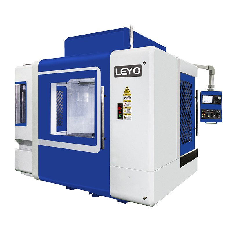 Eliminate part deflection and chatter. Master expert workholding strategies for vertical milling machines to maximize CNC precision and reduce scrap.Product news
 -
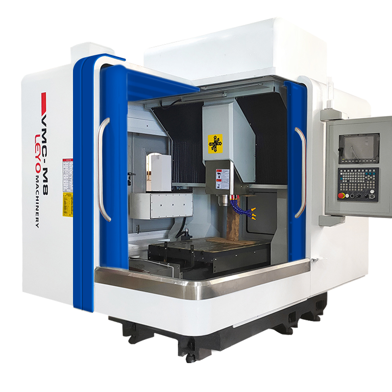 Stop tool breakage and scrap parts. Discover how horizontal milling machines use gravity for flawless chip evacuation and maximum ROI.Product news


