



Traditional 3-axis machining hides massive operational costs when processing complex parts. Moving a single workpiece across multiple fixtures introduces severe tolerance stack-up. Each manual refixturing step creates excessive idle time on the shop floor. Custom workholding expenses quickly eat into profit margins. The core manufacturing bottleneck is clear. You must achieve high-precision tolerances on multi-faceted geometries while facing intense pressure to compress lead times and reduce scrap rates. Factories must navigate skilled labor shortages by doing more with less. Transitioning to one-setup machining via a 5 axis machining center represents a strategic operational shift rather than just a hardware upgrade. This transition demands a strict technical evaluation of machine architectures, software requirements, and implementation realities.
Setup Reduction Equals Precision: Consolidating operations into a single setup eliminates the primary source of positional errors, directly improving true position and geometric dimensioning and tolerancing (GD&T) outcomes.
Architecture Dictates Application: Selecting between a compact 5 axis machining center, a trunnion-style machine, or a five axis gantry machining center depends strictly on part envelope, weight, and factory floor constraints.
Software is the Pacing Factor: Hardware capabilities are bottlenecked by CAM software proficiency, post-processor quality, and collision simulation accuracy.
Adoption Requires Upskilling: The true cost of implementation includes the learning curve for programmers and operators to manage simultaneous multi-axis toolpaths and advanced workholding.
The Economics and Mechanics of One-Setup Machining
Problem Framing: The Cost of Multiple Setups
Moving a part between different machines guarantees positional deviation. Tolerance stack-up is a mathematical reality on the shop floor. If a vise introduces a 0.001-inch error on the first setup, the second setup compounds that error. By the third operation, maintaining strict geometric dimensioning and tolerancing becomes nearly impossible. You lose true position accuracy every time an operator unclamps the workpiece. Consider a hydraulic manifold block requiring holes on all six sides. Machining this on a standard vertical mill requires at least six distinct setups. Each setup introduces a new datum shift.
Multiple setups also generate massive non-value-added time. Consider the hidden labor hours. An operator handles the part multiple times. They must blow off chips, stone the table, align the new fixture, and dial in the workpiece with an indicator. Every new setup requires a dedicated first-article inspection. Spindles sit idle during this entire process. These delays inflate cycle times and drastically reduce overall equipment effectiveness. You pay operators to move metal, not to indicate vises.
Defining "Done in One" and Axis Kinematics
One-setup machining physically changes how a cutting tool interacts with a part. Standard linear axes move in X, Y, and Z directions. A multi-axis machine adds two rotary axes. These are typically designated as A, B, or C. They allow the tool or the workpiece to articulate in five different directions. This kinematic freedom grants mechanical access to five sides of a prismatic part without human intervention. You load raw stock once, and a finished part comes out.
This capability targets complex geometries directly. You can machine compound angles, severe undercuts, and free-form surfaces. However, you must differentiate between 3+2 positional machining and full simultaneous contouring. In 3+2 machining, the machine indexes the rotary axes to a specific angle and locks the brakes. Cutting only occurs using the three linear axes. This works perfectly for complex manifold blocks or multi-sided housings where features sit on flat, angled planes.
Simultaneous multi-axis machining moves all five axes at the exact same time. The tool tip follows a continuously changing vector. This is strictly required for aerospace impellers, turbine blades, and organic shapes. The business case for each method depends entirely on your specific part complexity. Simultaneous motion requires significantly more processing power from the machine controller and advanced CAM programming skills.
ROI, Value Influencing Factors, and Over-Engineering
Evaluating the return on investment requires analyzing trade-offs. Multi-axis equipment carries a higher hourly burden rate than a standard vertical mill. However, it drastically reduces total cycle time. You eliminate the queue time between separate operations. Scrap reduction also drives ROI. Fewer setups mean fewer opportunities for operator error. Parts come off the machine finished and in tolerance. You also eliminate the need to design, machine, and store dozens of custom aluminum soft jaws for secondary operations.
You must also know when not to use this technology. Running simple, flat 3-axis prismatic parts on multi-axis equipment is financial inefficiency. If a part requires only one setup on a standard mill, continuous setup advantages are unnecessary. Over-engineering your production floor wastes valuable spindle hours. Reserve multi-axis equipment for parts that actually demand complex articulation or suffer from severe multi-setup bottlenecks.
Categorizing 5 Axis Machining Center Configurations
Trunnion Table vs. Swivel Head Architectures
Machine architecture dictates what you can successfully cut. Trunnion tables use a table-table configuration. The workpiece sits on a rotary platter that tilts inside a cradle. This design offers immense rigidity. It excels at heavy roughing and maintains excellent tool clearance. The A-axis tilts the cradle, while the C-axis rotates the platter. However, trunnions restrict the maximum part envelope. The workpiece must physically clear the machine walls and the spindle housing when the cradle tilts to 90 degrees.
Swivel head machines utilize a head-head configuration. The spindle itself articulates while the table remains stationary. This allows you to machine much heavier and larger parts. The table supports massive weight without stressing rotary bearings. Head-table configurations combine these approaches. The spindle tilts on one axis while the table rotates on another. You must evaluate rigidity, tool clearance, and part weight limitations against your specific production needs.
Table 1: Machine Architecture Comparison
| Configuration Type | Kinematic Movement | Primary Advantage | Ideal Application |
|---|---|---|---|
| Trunnion (Table-Table) | Workpiece tilts and rotates | Maximum rigidity and precision | Medium-sized complex aerospace components |
| Swivel Head (Head-Head) | Spindle tilts and rotates | Handles massive part weight | Large molds and heavy structural parts |
| Head-Table | Spindle tilts, table rotates | Versatile tool clearance | Mixed-batch manufacturing |
Space-Constrained Solutions: The Compact 5 Axis Machining Center
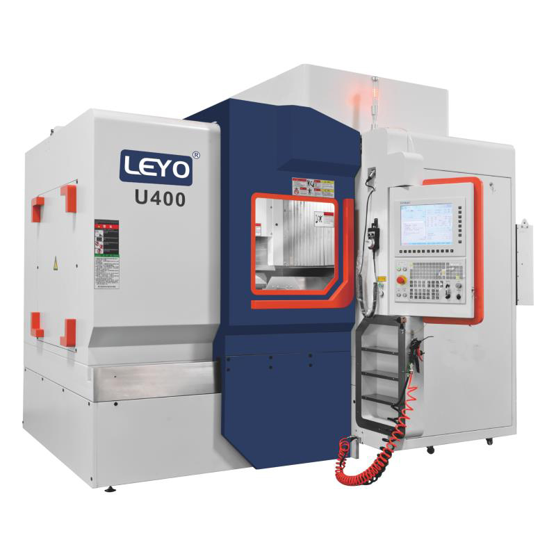
Factory floor space is often a premium commodity. Many shops cannot accommodate massive machine footprints. A compact 5 axis machining center solves this spatial constraint. These machines integrate coolant systems, tool changers, and chip management tightly within the main enclosure. They often fit into the exact same footprint as a standard 3-axis vertical mill, allowing shops to upgrade capabilities without pouring new concrete or rearranging the entire floor.
Compact models excel in specific use cases. They are ideal for medical device manufacturing, small intricate aerospace components, and rapid prototyping. However, you must accept certain trade-offs. Compact footprints inherently restrict axis stroke limits. Tool magazine capacity is often smaller, limiting the number of redundant tools you can load for lights-out manufacturing. Chip evacuation can also present challenges in tight enclosures during heavy material removal. You must balance the need for space against the physical requirements of your parts.
Scaling Up: Deploying a Five Axis Gantry Machining Center
Massive workpieces require entirely different structural solutions. When machining automotive dies, large aerospace structural components, or heavy casting molds, standard trunnions fail. The rotary bearings cannot handle the off-center mass. You must deploy a five axis gantry machining center to handle the scale. Gantry designs provide distinct structural advantages for oversized manufacturing.
In a gantry configuration, the table remains completely stationary. The massive workpiece does not move. Instead, an overhead gantry carries the articulating spindle across the part. This eliminates the dynamic shifting of heavy mass. Stationary tables combined with moving gantries maintain strict volumetric accuracy over extremely long travels. The machine structure easily absorbs the heavy cutting forces required for large-scale titanium or steel components. The foundation requirements for these machines are extensive, often requiring custom concrete pits to isolate vibrations.
Technical Evaluation Criteria for Machine Selection
Kinematics and Volumetric Accuracy
Precision over long machining cycles requires advanced feedback systems. Standard ball screws expand as they generate heat from friction. This thermal growth destroys tight tolerances. A ball screw can easily grow by 0.002 inches over a long roughing cycle. To combat this, evaluate machines equipped with absolute linear glass scales. These scales read the exact physical position of the axis, bypassing ball screw inaccuracies entirely. The controller reads the scale, not the motor encoder.
Rotary encoders perform the same function for the A, B, and C axes. They guarantee exact angular positioning. A deviation of just one-tenth of a degree at the rotary pivot point translates to a massive linear error at the tool tip. Dynamic thermal compensation is also critical. The machine controller monitors temperature sensors across the casting, spindle, and ball nut. It actively adjusts the toolpath to compensate for thermal expansion. These systems are mandatory for maintaining volumetric accuracy during multi-hour continuous cuts.
Spindle Specifications and Tool Clearance
Spindle selection dictates your material removal rate. You must match spindle torque and RPM to your primary materials. High-speed aluminum routing requires high RPM (often 20,000 to 30,000 RPM) and low torque. Conversely, high-torque titanium milling demands low RPM and massive low-end torque. Selecting the wrong spindle curve ruins tool life and limits productivity. You cannot efficiently hog out Inconel with a 24,000 RPM spindle designed for aluminum.
Spindle housing geometry is equally critical. Multi-axis toolpaths often drive the spindle deep into the part. A bulky spindle nose will collide with the workpiece walls or the workholding fixture. Slim spindle designs prevent collisions when machining deep cavities, compound angles, or severe undercuts. Always verify tool clearance limits before finalizing a machine specification. Look closely at the interference models provided by the machine builder.
Table 2: Spindle Selection Criteria by Material
| Material Type | Target RPM Range | Torque Requirement | Preferred Taper |
|---|---|---|---|
| Aluminum / Plastics | 15,000 - 30,000+ | Low | HSK-63A / HSK-63F |
| Mild Steel / Cast Iron | 8,000 - 15,000 | Medium | CAT40 / BT40 / HSK-63A |
| Titanium / Inconel | 4,000 - 8,000 | High | CAT50 / HSK-100A |
Workholding and Fixturing for 5-Sided Access
Traditional six-inch vises block access to the bottom of the part. One-setup machining requires an entirely new approach to fixturing. You must shift to zero-point clamping systems, dovetail fixtures, and self-centering multi-axis vises. These systems grip the part securely using minimal surface area. A zero-point system uses pull studs mounted to the bottom of a fixture plate. The machine table contains pneumatic or hydraulic receivers that pull the studs down with thousands of pounds of force, locking the fixture in place with extreme repeatability.
Elevating the workpiece is an absolute necessity. The part must sit high enough above the table to allow the spindle full articulation. If the part sits too low, the spindle housing will crash into the trunnion platter during severe tilt angles. Dovetail fixtures excel here. You prep the raw stock by milling a 45-degree dovetail on the bottom 0.125 inches of the material. The vise bites into this dovetail, holding it with massive clamping force while leaving the other five sides completely exposed for machining.
Software, Simulation, and Controller Requirements
CAM Integration and Post-Processing Realities
Hardware capabilities mean nothing without robust software. Your CAM system must generate clean, efficient multi-axis toolpaths. However, the post-processor is the actual pacing factor. The post-processor translates CAM data into the specific G-code your machine controller understands. A proven, error-free post-processor tailored to your exact machine kinematics is non-negotiable. If the post-processor outputs a rotary move in the wrong direction, the machine will crash.
Modern controllers require advanced features for efficient setup. Tool Center Point Control (TCPC) is mandatory. TCPC allows the controller to track the exact tip of the tool as the rotary axes move. Without TCPC, the CAM software must calculate the exact pivot length of the machine. With TCPC, the controller handles the kinematics, allowing the programmer to output a generic toolpath. Dynamic Work Offsets (DWO) allow operators to place a fixture anywhere on the table. The controller automatically recalculates the rotary pivot points based on the new location. Without TCPC and DWO, setup times skyrocket.
Collision Detection and Digital Twin Simulation
Multi-axis movements are incredibly difficult to visualize. The tool approaches the part from unpredictable angles. The risk of a catastrophic machine crash is high. You cannot rely on an operator hovering over the emergency stop button with their hand on the feed hold. Kinematic simulation software is a mandatory requirement. Programs like VERICUT read the exact G-code and simulate the machine's physical movements.
This creates a digital twin of your machining environment. The simulation verifies toolpaths before execution. It checks for gouges, fixture collisions, and over-travel limits. It models the exact spindle housing, the tool holder, the cutting tool, and the workholding. Digital twins mitigate financial risk during the programming phase. They ensure the program is safe before the machine ever powers on, protecting your spindle bearings from a high-speed impact.
Implementation Risks and Adoption Challenges
Operator Skill Gaps and Training Timelines
Transitioning a standard 3-axis machinist to a multi-axis workflow involves a steep learning curve. The nature of the labor shifts dramatically. Operators spend less time manually refixturing parts and more time managing advanced digital setups. They must understand rotary pivot points, tool vectors, and complex probing routines. They need to know how to recover a machine if it stops mid-cut during a simultaneous 5-axis toolpath.
You must provide realistic timelines for training. Reaching baseline productivity rarely happens in a week. Expect programmers to need several months to master simultaneous toolpaths and collision avoidance strategies. Operators need dedicated time to understand zero-point workholding and dynamic offsets. Investing heavily in upfront training prevents expensive scrap and machine downtime later.
Send lead programmers to dedicated CAM software training focused strictly on multi-axis toolpaths.
Train operators on the specific controller functions, focusing heavily on TCPC and DWO activation.
Establish a strict protocol for running digital twin simulations before any new program hits the floor.
Implement a standardized workholding strategy using zero-point plates to minimize setup variations.
Maintenance, Calibration, and Uptime
Adding rotary axes increases mechanical complexity. Bearings wear out. Backlash develops over time in the worm gears. You must implement routine kinematic calibration to maintain precision. Modern machines use probe-based automated tuning. The spindle probe touches a calibration sphere mounted to the table at various rotary angles. The controller then updates the kinematic parameters automatically, adjusting for any mechanical wear or settling in the casting.
Environmental requirements also play a major role in uptime. You cannot maximize the inherent precision of this equipment in a fluctuating environment. Temperature-controlled facilities are necessary. If ambient shop temperatures swing wildly between morning and afternoon, the machine casting will expand and contract. A ten-degree temperature swing can easily push a tight-tolerance aerospace part out of spec. Control your shop environment to control your part quality.
Conclusion
Request a detailed time study from potential machine tool builders based on your specific part models.
Provide your most problematic multi-setup part for a physical test cut to validate cycle time claims.
Audit your current CAM software capabilities and programmer proficiency to identify training gaps before the machine arrives.
Standardize your shop's workholding around a zero-point clamping system to maximize the new machine's uptime.
FAQ
Q: What do the 5 axes actually represent in a 5 axis machining center?
A: The first three axes are the standard linear axes—X, Y, and Z. These move the tool left-right, forward-backward, and up-down. The additional two are rotary axes, typically designated as A, B, or C. These rotary axes rotate around the linear axes, allowing the machine to tilt the tool or the table to access different angles.
Q: What is the difference between 3+2 machining and simultaneous 5-axis machining?
A: In 3+2 machining, the machine locks the rotary axes into a specific position before cutting begins. The tool only moves along the X, Y, and Z axes during the cut. Simultaneous machining moves all five axes continuously at the same time. This is required for complex contours like turbine blades and free-form surfaces.
Q: How much floor space does a compact 5 axis machining center require?
A: Footprints vary by manufacturer, but compact models typically require between 50 to 80 square feet. They integrate coolant tanks and chip management tightly within the main enclosure. This allows them to fit within the same floor space typically occupied by a standard 3-axis vertical machining center.
Q: What are the limitations of one-setup machining?
A: The primary limitation is the "sixth side" problem. The face where the workholding fixture grips the part remains inaccessible during the main machining cycle. This bottom face still requires a secondary operation, a parting-off process, or a dedicated fixture to finish the final side of the component.
Q: When is a five axis gantry machining center strictly necessary?
A: A gantry machine is necessary when part weight and travel requirements exceed the physical capacities of a trunnion table. This is typically seen in large aerospace bulkheads, massive automotive molds, or heavy structural castings where moving the part dynamically would cause severe inaccuracy.
Q: How does a 5-axis machine improve part accuracy?
A: It improves accuracy by eliminating tolerance stack-up. Every time an operator moves a part to a new fixture, alignment errors occur. By machining five sides in a single setup, you remove human error and fixture deviations, ensuring features remain perfectly true to one another.
Q: What is the typical ROI period for a 5-axis CNC machine?
A: ROI is calculated based on reduced setup times, lower scrap rates, and the ability to bid on more complex contracts. Depending on machine utilization and contract value, the typical ROI period ranges from 18 to 36 months for most manufacturing environments.
Related Articles
-
 Dear Customers and Business Partners,In order to strictly comply with national export control laws and regulations, and to fulfill international obligations, ensuring that our exported CNC milling machines and CNC lathes are fully legal and compliant, we hereby notify you of the relevant policies coCompany News
-
 Abrasive graphite dust destroys standard CNCs. Learn why specialized dust-proof machines and proper wet or dry milling methods are essential for safe EDM electrode production.Product news
-
 Drill tap centers deliver high-speed threading for high-volume production. Understanding spindle torque limits prevents costly tool breakage and optimizes machine cycle times.Product news


