



A CNC Milling Machine is an automated subtractive manufacturing tool that uses computer-controlled rotating cutting tools to remove material from a solid block, shaping it into a precise custom part. Modern manufacturing demands exact precision, absolute repeatability, and rapid production speeds. Manual machining simply cannot keep pace with these strict requirements. Automated subtractive processes have become the standard for producing complex geometries with tight tolerances. Engineering and procurement teams constantly evaluate manufacturing methods to optimize production. You must balance tight tolerance requirements, material versatility, and production output without over-investing in unnecessary machine capabilities. Choosing the right equipment prevents bottlenecks and reduces wasted capital. This technical guide breaks down specific applications, material constraints, and machine configurations. You will learn how to evaluate vertical versus horizontal setups and determine exactly when and how to leverage CNC milling for your production floor.
Subtractive Precision: CNC milling machines utilize pre-programmed computer code (G-code) to automate multi-axis material removal, achieving tolerances as tight as ±0.0005 inches.
Broad Application Spectrum: Applications range from rapid prototyping of complex geometries to full-scale production of aerospace, automotive, and medical components.
Configuration Dictates Capability: The choice between a vertical CNC milling machine and a horizontal or 5-axis setup fundamentally alters production volume capacity, footprint, and upfront capital requirements.
Strategic Procurement: Deciding to invest in a CNC milling machine requires evaluating facility readiness, CAD/CAM software integration, and the availability of skilled operators versus the operational expenditure of outsourcing.
The Mechanics of Subtractive Manufacturing: How a CNC Milling Machine Operates
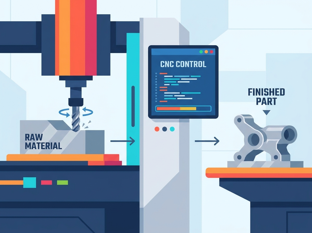
Subtractive manufacturing removes material to create a final shape. This contrasts directly with additive manufacturing, like 3D printing, which builds parts layer by layer. CNC milling automates this subtractive process, eliminating the inconsistencies inherent in manual machining. When you stand in front of a running machine, you see a highly orchestrated sequence of movements. Every plunge, contour, and retraction happens because a computer dictates the exact position of the cutting tool relative to the raw stock.
Computer Numerical Control (CNC) and G-Code Translation
The workflow begins with Computer-Aided Design (CAD) software. Engineers create a 3D model of the desired part, defining every dimension, fillet, and chamfer. Computer-Aided Manufacturing (CAM) software then analyzes this model to generate toolpaths. The CAM programmer selects the appropriate end mills, face mills, and drills, assigning specific speeds and feeds based on the material. The CAM software outputs G-code, the standard programming language for CNC equipment.
The machine controller reads this G-code line by line. It translates spatial coordinates into precise electrical signals. These signals drive the spindle speed, dictate the feed rate, and guide the cutting tool along exact paths to carve the raw material. The controller also manages auxiliary functions, such as turning on the flood coolant or activating the chip conveyor. A standard program might contain tens of thousands of lines of code, executing complex 3D surfacing operations that would be impossible to replicate by hand.
Technical Anatomy: Key Components of a CNC Milling Machine
The spindle is the rotating heart of the machine. It holds the cutting tool and dictates the cutting speed. Spindle tapers, such as CAT40 or BT30, determine the tooling compatibility and rigidity during heavy material removal. A CAT40 spindle, for example, offers significant mass and rigidity, allowing operators to push large face mills through tough alloy steels without stalling the motor or inducing chatter.
The controller acts as the brain. It provides the hardware interface where operators load programs, set tool offsets, and monitor the machining process. Axis drives and precision ball screws work together to convert rotary motor motion into smooth linear travel. This system ensures minimal backlash and high positional accuracy. When the controller commands a movement of 0.001 inches, the servomotors rotate the exact amount required to drive the ball nut along the screw, positioning the heavy cast-iron table with absolute certainty.
An Automatic Tool Changer (ATC) drastically reduces cycle times. Drum or carousel-style changers swap cutting tools in seconds without operator intervention. Meanwhile, the workpiece must remain entirely rigid. The machine bed, equipped with T-slots, utilizes vises and custom fixtures to secure the raw material stock against heavy cutting forces. Operators frequently use precision ground machinist vises, soft jaws machined to match the part profile, or vacuum chucks for thin plate work.
Multi-Axis Movement and Material Removal Rates (MRR)
Material Removal Rate (MRR) measures the volume of material carved away per minute. MRR is a critical metric for calculating production cycle times and optimizing the cost-per-part. A rotating cutting tool advances into a stationary or moving workpiece, shearing away chips. Higher MRR requires rigid machine structures and powerful spindle motors to prevent harmful vibrations.
Calculating MRR involves multiplying the depth of cut, the width of cut, and the feed rate. Shop floor managers constantly push to maximize MRR without compromising tool life or surface finish. Modern tooling strategies, such as high-efficiency milling (HEM), utilize the entire flute length of the end mill while taking a lighter radial step-over. This approach maintains a high MRR while distributing wear evenly across the cutting tool, extending its lifespan and reducing tooling costs.
Primary CNC Milling Operations: Cutting, Shaping, and Drilling
Milling centers perform diverse operations within a single setup. Understanding these operations helps programmers select the right tooling and optimize toolpaths. A single block of aluminum might undergo a dozen different operations before it becomes a finished bracket.
Face Milling
Face milling removes material from the flat top surface of a workpiece. The cutting tool rotates on an axis perpendicular to the workpiece surface. This operation creates flat planes and establishes a smooth surface finish before subsequent features are machined. Machinists typically use large-diameter face mills with multiple carbide inserts. These tools cover a wide area in a single pass, quickly squaring up raw stock and establishing a reliable datum surface for the rest of the machining process.
Pocket and Profile Milling
Pocket milling creates internal cavities to specified depths. The tool plunges into the material, often using a helical ramping motion to clear chips, and clears out a defined boundary. Profile milling targets the external contours of the part. Both operations require precise toolpath strategies to manage chip load and prevent tool breakage. Climb milling, where the cutter rotates in the direction of the feed, is generally preferred for these operations because it yields a superior surface finish and directs cutting forces down into the rigid machine table.
Drilling, Boring, and Reaming
Hole-making involves several distinct steps. Drilling creates the initial rough hole using a standard twist drill or a high-performance carbide drill with through-tool coolant. Boring uses a single-point cutting tool mounted in an adjustable boring head to enlarge an existing hole, ensuring precise concentricity and location. Reaming follows drilling or boring to achieve micro-tolerances and exceptionally smooth internal walls. A reamer removes only a tiny amount of material, sizing the hole perfectly for press-fit dowel pins or bearing races.
Thread Milling and Tapping
Creating internal and external threads requires specialized techniques. Thread milling uses a rotating multi-point tool interpolating in a helical path. It offers superior structural integrity and allows one tool to cut various thread sizes. If a thread mill breaks, you can easily extract it from the hole. Traditional tapping drives a dedicated tap directly into a hole, which is faster but risks part damage if the tap breaks. Extracting a broken high-speed steel tap from a titanium workpiece often requires specialized electrical discharge machining (EDM), causing severe production delays.
| Operation | Tooling Used | Primary Purpose | Risk Factor |
|---|---|---|---|
| Face Milling | Insert Face Mill | Flattening large surfaces, establishing datums | Low (High rigidity) |
| Pocket Milling | Solid Carbide End Mill | Clearing internal cavities | Medium (Chip evacuation issues) |
| Boring | Single-Point Boring Head | Precise hole sizing and location | High (Requires exact setup) |
| Thread Milling | Carbide Thread Mill | Creating internal/external threads | Low (Easy tool extraction) |
Core Industrial Applications: What Is a CNC Milling Machine Used For?
Machine capabilities directly dictate industry-standard output requirements. Different sectors leverage milling technology to achieve specific mechanical outcomes. The versatility of the equipment allows a single machine shop to serve wildly different markets simply by changing the tooling and the raw material.
Aerospace and Automotive: High-Tolerance Prototyping and Production
Aerospace and automotive sectors demand high-tolerance prototyping and rigorous production. Milling centers produce engine components, landing gear parts, and custom structural brackets. These components require exact dimensional accuracy to ensure structural integrity while maximizing weight reduction. Engineers frequently design aerospace parts with thin walls and deep pockets to remove unnecessary mass. Machining these features from solid billets of 7075 aluminum or titanium requires advanced toolpath strategies to prevent the thin walls from vibrating or deflecting away from the cutter.
Medical Device Manufacturing: Biocompatible Materials and Micro-Machining
Medical manufacturing relies heavily on biocompatible materials and micro-machining. Milling machines produce surgical instruments, orthopedic implants, and equipment enclosures. These parts demand strict FDA-compliant surface finishes and zero-defect manufacturing processes. A titanium bone plate, for example, must have perfectly smooth contoured surfaces to prevent tissue irritation. Machinists use miniature end mills, sometimes less than 0.010 inches in diameter, running at extremely high spindle speeds to carve intricate features into medical devices.
Custom Tooling, Jigs, and Fixtures for Production Lines
Manufacturers frequently use milling centers internally to support broader production lines. They machine custom workholding equipment, assembly jigs, and inspection fixtures. Accurate fixtures ensure that subsequent manufacturing steps remain consistent and repeatable. If an assembly line requires workers to press two components together, a CNC-milled aluminum nest ensures the parts align perfectly every single time. Investing machine time into building robust internal tooling pays massive dividends in overall factory throughput and quality control.
Material Capabilities and Machining Constraints
Milling centers handle a vast spectrum of materials. Each material requires specific tooling, speeds, and feeds to machine successfully. You cannot cut stainless steel using the same parameters you use for soft plastics. Understanding material behavior under a cutting load is fundamental to successful manufacturing.
Metals and Alloys (Aluminum, Titanium, Steel)
Aluminum offers excellent machinability and allows for high-speed material removal. It dissipates heat well and produces manageable chips. Steel and titanium provide superior strength but present significant machining challenges. Milling hardened steels or titanium requires highly rigid machine setups, specialized carbide tooling with advanced coatings like Titanium Aluminum Nitride (TiAlN), and high-pressure coolant systems to manage extreme heat generation. Titanium, in particular, has a tendency to work-harden if the cutting tool rubs against the material instead of shearing it cleanly. Operators must maintain a constant, aggressive feed rate to stay ahead of the work-hardened zone.
Engineering Plastics and Composites
Plastics like PEEK, Delrin, and polycarbonate are common in modern manufacturing. However, milling plastics introduces unique challenges. Excessive spindle speeds generate heat that causes material deformation or melting. Sharp tooling and optimized feed rates are essential to shear the plastic cleanly without inducing thermal stress. Machinists often use uncoated, highly polished carbide end mills for plastics to prevent the material from sticking to the flutes. When machining composites like carbon fiber or G10 fiberglass, the abrasive nature of the material rapidly degrades standard tooling. Diamond-coated end mills and specialized dust collection systems are mandatory to maintain tolerances and protect the machine's linear guideways from abrasive dust.
Wood, Glass, and Specialized Substrates
Softer materials and brittle substrates require different approaches. CNC routers typically handle wood, utilizing higher spindle speeds and lighter cuts. Machining glass or ceramics requires specialized diamond-impregnated tooling and continuous flood coolant to prevent fracturing. You cannot use standard fluted end mills on glass; instead, you use grinding pins that abrade the material away slowly. The machine must be entirely enclosed to contain the abrasive slurry, and the coolant filtration system must be robust enough to capture microscopic glass particles before they damage the coolant pump.
| Material Category | Common Examples | Machinability | Primary Challenge |
|---|---|---|---|
| Soft Metals | 6061 Aluminum, Brass | Excellent | Chip packing in deep pockets |
| Hard Alloys | Titanium, Inconel, 4140 Steel | Poor to Fair | Extreme heat generation, rapid tool wear |
| Engineering Plastics | Delrin, PEEK, Nylon | Good | Material melting, dimensional instability |
| Composites | Carbon Fiber, G10 Garolite | Fair | Highly abrasive dust, delamination |
Evaluating Machine Configurations for Your Production Floor
Buyers must align equipment specifications with their specific part geometries and volume targets. The machine architecture dictates what you can efficiently produce. Purchasing the wrong configuration leads to excessive setup times, operator frustration, and missed production deadlines.
The Vertical CNC Milling Machine: Ideal Use Cases and Limitations
A vertical CNC milling machine features a spindle axis oriented vertically. The tool points downward toward the machine table. This configuration is the industry standard for single-sided parts, flat plate work, and operations requiring frequent manual tool changes or setups. Vertical mills generally require a smaller floor footprint and present a lower upfront capital requirement compared to horizontal alternatives. Operators find vertical machines highly intuitive because they can look directly down onto the workpiece while setting up fixtures or proving out a new program. However, when machining deep pockets, gravity keeps the metal chips trapped inside the cavity, requiring high-pressure coolant or air blasts to clear the cutting zone and prevent recutting chips.
Horizontal CNC Mills: High-Volume and Heavy-Duty Applications
Horizontal mills orient the spindle parallel to the floor. This design excels in high-volume and heavy-duty applications. Gravity assists with chip evacuation, pulling metal chips away from the cutting zone during heavy cuts. Horizontal machines often utilize tombstones, allowing operators to mount multiple parts on different faces for highly efficient multi-sided machining. A horizontal machining center (HMC) equipped with a pallet pool can run continuously for hours. While one pallet is inside the machine cutting parts, the operator unloads finished components and loads fresh raw stock onto a second pallet outside the machine. This eliminates spindle downtime during part changeovers.
3-Axis vs. 4-Axis vs. 5-Axis: Complexity vs. Setup Time Trade-offs
Standard 3-axis milling moves the tool along the X, Y, and Z planes. Adding a 4th axis introduces rotation around the X or Y axis, typically via a rotary table. A 5-axis machine allows the tool to approach the workpiece from virtually any angle by tilting the spindle or trunnion table. Upgrading to 5-axis continuous milling reduces the hidden costs of multiple manual setups and is essential for highly complex part geometries like turbine impellers. Every time an operator unclamps a part and flips it over for a secondary operation, they introduce a small amount of positional error. A 5-axis machine allows you to machine five sides of a block in a single clamping, ensuring perfect alignment between all features.
Decision Framework: In-House CNC Milling vs. Outsourced Manufacturing
Adopting CNC technology introduces distinct operational realities. You must weigh the benefits of internal control against the flexibility of outsourcing. Bringing manufacturing in-house is a massive commitment that alters the fundamental structure of your business.
Capital Expenditure (CapEx) vs. Operating Expenditure (OpEx)
Purchasing a machine requires significant Capital Expenditure (CapEx). You must account for the machine, tooling, maintenance, and facility upgrades. Outsourcing shifts this to Operating Expenditure (OpEx), where you pay a contract manufacturer a per-part rate. High-volume, recurring production often justifies the CapEx of internal equipment. If you consistently spend tens of thousands of dollars a month on machined parts, financing a machine tool quickly becomes cash-flow positive. However, if your demand is sporadic or highly unpredictable, tying up capital in heavy machinery creates unnecessary financial risk.
Facility Requirements, Maintenance, and Operator Expertise
Installing a milling center requires specific facility infrastructure. You need robust 3-phase power, climate control for thermal stability, and clean compressed air systems. A standard commercial air compressor is rarely sufficient; you need a rotary screw compressor with a refrigerated air dryer to prevent moisture from destroying the machine's pneumatic valves. Furthermore, operating the equipment demands skilled labor. You must factor in the resources required to hire or train competent CNC programmers and operators. The manufacturing industry faces a severe shortage of skilled machinists. Finding personnel who can read complex blueprints, program CAM software, and troubleshoot machining chatter is often the hardest part of bringing production in-house.
Scalability and Lead Time Control
In-house milling provides absolute control over production schedules. It protects sensitive intellectual property and drastically accelerates R&D iteration cycles. When engineers can design a part in the morning and hold a machined prototype in the afternoon, the pace of innovation skyrockets. Conversely, outsourced machine shops offer infinite scalability. They can absorb sudden spikes in production demand without requiring you to purchase additional equipment. If you need ten thousand parts next month, a large contract manufacturer simply allocates more machines to your job. If you rely solely on internal capacity, you are strictly limited by the number of spindles on your floor and the hours in a day.
Conclusion
Audit your facility's current electrical and pneumatic infrastructure to ensure compatibility with industrial milling equipment before making a purchase.
Conduct a comprehensive part-cost analysis comparing internal production cycle times against current outsourcing quotes to determine financial viability.
Evaluate your typical part geometries to determine if a vertical setup suffices or if a 5-axis machine is necessary to eliminate secondary setups.
Consult with a manufacturing engineer to map out a phased implementation plan for CAD/CAM software integration and operator training.
FAQ
Q: What is the difference between a CNC milling machine and a CNC lathe?
A: Milling uses a spinning cutting tool against a stationary or moving workpiece to create flat surfaces and complex shapes. Turning, performed on a lathe, spins the workpiece itself against a stationary cutting tool to create cylindrical parts.
Q: What is the typical tolerance of a vertical CNC milling machine?
A: Industry standard tolerances typically range from ±0.001 to ±0.0005 inches. Achieving these tight tolerances depends heavily on machine rigidity, high-quality tooling, and strict thermal control within the facility.
Q: What materials cannot be milled on a standard CNC machine?
A: Highly brittle materials, such as certain advanced ceramics or tempered glass, cannot be milled without specialized diamond tooling. Highly flexible rubbers are also unsuitable because they deform under cutting pressure instead of shearing cleanly.
Q: How long does it take to program a CNC mill?
A: Simple 2D profiles can take just minutes to program using modern CAM software. However, complex 5-axis aerospace components may require several days of intricate programming, toolpath optimization, and collision simulation.
Q: Can a CNC milling machine operate unattended?
A: Yes, unattended or lights-out manufacturing is possible. It requires specific machine upgrades, including automatic pallet changers, laser tool breakage sensors, high-pressure coolant systems, and robotic part loaders to function safely without an operator.
Related Articles
-
 Dear Customers and Business Partners,In order to strictly comply with national export control laws and regulations, and to fulfill international obligations, ensuring that our exported CNC milling machines and CNC lathes are fully legal and compliant, we hereby notify you of the relevant policies coCompany News
 -
 Understanding which machine tool is best suited for machining which material can assist machining factories and machine tool agents in making the optimal choice. This article introduces the materials that can be most effectively machined by CNC milling machines, CNC lathes, and CNC machining centers.CNC Machine Industry News
 -
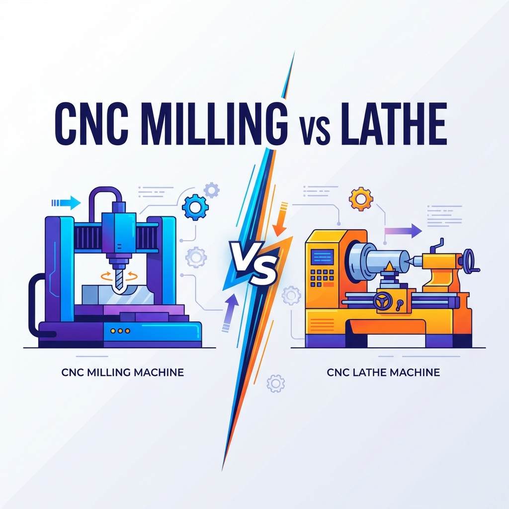 Compare CNC milling vs. turning. Learn differences in kinematics, geometry, cost, and automation to select the right machine for your production.Product news


