



The transition from manual milling to computer numerical control represents a massive shift in subtractive manufacturing. It enables repeatable, high-tolerance part production at scale. A CNC Milling Machine automates material removal from a raw block using rotating multi-point cutting tools guided by programmed instructions. This technology forms the backbone of modern industrial production.
Misaligning part complexity, material requirements, and production volume with the wrong machine specifications leads to bloated capital expenditures, excessive setup times, and compromised part quality. Selecting equipment with inadequate rigidity forces engineering teams into continuous workarounds. This ultimately degrades overall throughput. Over-specifying a machine results in underutilized assets and wasted resources.
Understanding the precise mechanics, axis configurations, and operational limitations of a milling platform is mandatory. Engineering and procurement teams must evaluate whether to invest in internal equipment or contract a specialized CNC machining center. Mastering these fundamentals helps organizations align manufacturing strategies with actual production demands.
Subtractive Precision: CNC milling machines utilize automated, rotating cutting tools to remove material from a stationary or multi-axis rotating workpiece, achieving tolerances often tighter than ±0.0005 inches.
Configuration Dictates Capability: The choice between 3-axis, 4-axis, and 5-axis machines directly impacts setup frequency, tooling access, and the ability to machine complex organic geometries.
Strategic Sourcing: High-mix, low-volume production often favors outsourcing to an established CNC machining center, whereas high-volume, proprietary part production justifies in-house machine acquisition.
The Mechanics: How a CNC Milling Machine Works
Subtractive manufacturing operates on a completely different principle than additive processes like 3D printing. Instead of building a part layer by layer, a milling machine starts with a solid block of raw material. We call this a billet or workpiece. Through the application of high-speed rotational cutting tools, the machine systematically shears material away until only the desired final geometry remains. This process creates robust, homogenous parts with exceptional structural integrity.
The direct cutting interface relies on a spinning, cylindrical cutting tool driven along multiple programmed toolpaths. Tools such as end mills, face mills, and drills carve specific geometries into the workpiece. Face mills rapidly clear large flat areas. Smaller end mills cut intricate slots, deep pockets, precise holes, and complex 3D contours. The interaction between the cutting edge and the workpiece generates chips. These chips effectively carry heat away from the cutting zone, protecting the metallurgical properties of the final part.
Workpiece material diversity dictates the operational parameters required for successful milling. Different materials demand specific spindle speeds, feed rates, and tooling geometries. Machining aluminum requires high RPMs and aggressive feed rates to prevent material from welding to the tool. Cutting tough alloys like stainless steel or titanium necessitates rigid setups, lower spindle speeds, and high torque to overcome the material's shear strength. Engineering plastics such as POM, PEEK, and nylon require sharp tooling and careful thermal management to prevent melting or warping during the cutting process.
| Material Type | Typical Spindle Speed (RPM) | Tooling Requirement | Coolant Strategy |
|---|---|---|---|
| Aluminum (6061-T6) | 10,000 - 15,000+ | Uncoated Carbide, 2-3 Flutes | High-pressure flood or mist |
| Stainless Steel (304/316) | 3,000 - 6,000 | TiAlN Coated Carbide, 4-5 Flutes | Heavy flood coolant |
| Titanium (Ti-6Al-4V) | 1,000 - 3,000 | Specialty Coated, High Helix | High-pressure through-spindle |
| Engineering Plastics (PEEK) | 6,000 - 10,000 | Highly Polished, Sharp Edge | Air blast or light mist |
The software-to-hardware translation process bridges the gap between digital intent and physical execution. The workflow follows a strict sequence:
The engineering team creates a 3D CAD model of the desired part.
The model is imported into CAM (Computer-Aided Manufacturing) software.
The programmer selects cutting tools, speeds, and feeds within the CAM environment.
The CAM software generates optimized toolpaths based on the selected parameters.
The software post-processes this data into G-code.
G-code is the standardized programming language that dictates motion control. It tells the machine exactly where to move in three-dimensional space. M-codes handle machine function controls. These include activating high-pressure coolant, triggering tool changes, and controlling spindle direction.
Modern milling platforms rely on closed-loop feedback systems to maintain absolute precision. Servo motors drive the ball screws that move the machine axes. High-resolution glass scales or rotary encoders constantly monitor the actual physical position of those axes. This positional data feeds back to the machine controller in real-time. If the controller detects any discrepancy between the programmed coordinates and the actual tool position, it instantly applies corrective micro-adjustments. This continuous feedback loop mitigates mechanical backlash and ensures the machine hits exact tolerances regardless of cutting forces or thermal expansion.
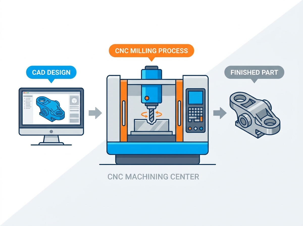
Core Components of a Modern CNC Machining Center
The evolution of subtractive manufacturing has blurred the lines between a basic milling machine and a comprehensive production platform. A standard milling machine typically features an open architecture. It requires significant manual intervention for tool changes and chip management. A modern machining center is a fully enclosed system integrated with automatic tool changers, high-pressure through-spindle coolant systems, and automated chip conveyors. These integrations transform the equipment from a simple cutting tool into a continuous production asset capable of running lights-out operations.
The Machine Control Unit acts as the brain of the entire system. It interprets the G-code and orchestrates the synchronized movement of all servo motors and auxiliary systems. Control architectures generally fall into two categories. Proprietary controls developed by the machine builder often feature conversational programming interfaces optimized for their specific hardware. Industry-standard open architectures like FANUC or Siemens offer universal familiarity. This makes it easier to recruit operators who already possess the required programming knowledge.
Spindle dynamics determine the material removal rates a machine can achieve. The spindle holds and rotates the cutting tool. Its performance is defined by its RPM capabilities, torque curve, and taper type. High-speed spindles exceeding 15,000 RPM are ideal for fast, light cuts in aluminum and plastics. High-torque spindles operating at lower RPMs are necessary for heavy roughing in tool steels and superalloys. The taper type dictates the rigidity of the tool connection. HSK tapers expand at high speeds to grip the tool holder more tightly. This provides superior runout characteristics during high-speed machining compared to standard CAT40 tapers.
The Automatic Tool Changer (ATC) drastically reduces cycle times. It eliminates the need for operator intervention between different machining operations. Carousels and side-mount ATCs store anywhere from a dozen to over a hundred pre-measured cutting tools. When the program calls for a new tool, the ATC swaps the current tool in the spindle with the requested tool in a matter of seconds. This capability allows a single machine to perform facing, roughing, finishing, drilling, and tapping operations in a single, uninterrupted setup.
The foundation of the machine's movement relies on its guideway system. The choice between linear guideways and box ways fundamentally impacts the machine's application.
Box Ways: These feature solid, rectangular guides that provide maximum surface contact. They offer exceptional rigidity and superior vibration dampening. This makes them the preferred choice for heavy, interrupted cutting in hard materials like titanium and Inconel.
Linear Guideways: These utilize recirculating ball bearings or rollers on profiled rails. They offer significantly less friction, enabling faster rapid traverse rates and higher acceleration. Linear guides are ideal for high-speed machining applications where agility and contouring speed are prioritized over brute cutting force.
Axis Configurations and Production Capabilities
The number of programmable axes on a milling machine defines its geometric capabilities. It directly influences the manufacturing strategy. Selecting the correct configuration is essential for optimizing setup times and achieving the required part accuracy.
3-Axis Milling (X, Y, Z)
In a 3-axis configuration, the cutting tool moves across three linear axes: X (left and right), Y (forward and backward), and Z (up and down). The workpiece remains stationary on the machine table. This setup is highly effective for producing flat, 2.5D parts, simple brackets, and base plates. The primary limitation of 3-axis milling is tooling access. If a part requires features machined into multiple faces, the operator must manually stop the machine, unclamp the part, rotate it, and re-establish the work coordinate system. Each manual setup introduces the potential for stacking tolerances and positional errors.
4-Axis Milling (Addition of A-Axis)
A 4-axis machine incorporates the standard X, Y, and Z linear movements while adding a rotational axis. This is typically the A-axis, which rotates around the X-axis. You usually achieve this by mounting a rotary table or indexer to the machine bed. The addition of the fourth axis allows the machine to access multiple sides of a workpiece without manual intervention. It is particularly advantageous for machining cylindrical features and performing continuous cutting around a cylinder. It reduces setups by exposing up to four faces of a prismatic block to the cutting spindle in a single operation.
5-Axis Milling (Addition of B or C-Axis)
5-axis milling represents the highest level of subtractive geometric capability. These machines add two rotational axes to the standard three linear axes. The configuration can involve a tilting rotary table (trunnion) or an articulating spindle head. In 3+2 positional machining, the rotational axes orient the part to a specific angle, lock into place, and the cutting is performed using the three linear axes. In full 5-axis simultaneous machining, all five axes move continuously and concurrently. This capability is essential for manufacturing aerospace impellers, complex medical implants, turbine blades, and intricate organic geometries. The trade-offs include a significantly higher initial capital investment, the requirement for advanced CAM programming software, and the need for highly skilled operators to manage complex toolpath verification and collision avoidance.
| Axis Configuration | Primary Motion | Best Application | Setup Efficiency |
|---|---|---|---|
| 3-Axis | X, Y, Z Linear | Flat plates, simple brackets | Low (Requires manual flipping) |
| 4-Axis | X, Y, Z + A (Rotation) | Cylindrical parts, multi-face blocks | Medium (Accesses 4 sides) |
| 5-Axis (3+2) | X, Y, Z + B, C (Positional) | Complex multi-sided parts | High (Accesses 5 sides) |
| 5-Axis (Simultaneous) | All 5 axes move together | Impellers, turbine blades | Very High (Complex contours) |
Evaluating CNC Milling Machines for Your Production Floor
Procuring the right equipment requires a systematic evaluation of current and future manufacturing demands. Failing to align machine specifications with actual production needs results in severe operational inefficiencies.
Problem framing establishes the success criteria for the investment. Engineering and procurement teams must define production requirements based on material hardness, required dimensional tolerances, surface finish specifications, and projected batch sizes. A facility producing high volumes of small, tight-tolerance aluminum enclosures requires a vastly different machine architecture than a shop focused on low-volume, heavy-duty steel molds. Establishing these parameters prevents the acquisition of mismatched technology.
A features-to-outcomes matrix helps translate technical specifications into tangible production benefits. Evaluating specific machine characteristics against desired results ensures the investment targets the right operational metrics.
High Torque/Low RPM: Outcome = Efficient, chatter-free machining of tool steels and superalloys without stalling the spindle or inducing excessive tool wear.
High RPM/Low Torque: Outcome = Superior surface finishes and exceptionally fast cycle times on aluminum, brass, and engineered plastics.
Thermal Compensation: Outcome = Maintained volumetric accuracy during long, continuous production runs, automatically adjusting for structural expansion as the machine casting heats up.
Scalability and automation must be factored into the evaluation process. As production volumes increase, the machine must support automated workflows. Assessing the integration capabilities for pallet pools allows parts to be loaded outside the machine envelope while the spindle remains active. Robotic part loading systems and high-pressure through-spindle coolant are critical features for enabling reliable, lights-out manufacturing shifts. This maximizes overall equipment effectiveness.
Implementation Realities and Hidden Costs
Deploying advanced manufacturing equipment involves logistical and infrastructural challenges that extend far beyond the delivery of the machine itself. Preparing the production environment is a critical phase of implementation.
Facility requirements dictate the physical environment necessary for the machine to operate within its stated specifications. High-performance milling centers require reinforced concrete foundations of specific depths. This prevents the transfer of harmonic vibrations during heavy cutting. The facility must supply stable 3-phase power, high-volume clean compressed air, and adequate ventilation. For applications demanding micron-level precision, the machine must be housed in a strictly climate-controlled environment. Ambient temperature fluctuations will cause the machine casting and the workpiece to expand and contract, destroying dimensional accuracy.
Tooling and workholding capital expenditures represent a significant, often underestimated, portion of the total investment. A bare machine cannot produce parts. Equipping the platform requires high-quality precision vises, custom zero-point fixture plates, balanced tool holders, and an extensive inventory of carbide or diamond-coated end mills. These essential accessories routinely add substantial percentage points to the initial machine investment and must be factored into the upfront budget allocation.
Talent acquisition presents a severe operational risk in the current manufacturing landscape. The skilled labor shortage means that acquiring the hardware is often easier than finding the personnel to run it. Operating complex multi-axis equipment requires hiring or extensively training personnel capable of advanced CAM programming, macro variable logic, and deep machine troubleshooting. Without competent programmers and setup technicians, even the most advanced machine will fail to deliver its projected output.
In-House Investment vs. Outsourcing to a CNC Machining Center
Deciding whether to build internal manufacturing capacity or leverage external suppliers is a strategic crossroad. This decision hinges on capital allocation, risk tolerance, and production volume stability.
A rigorous capital expenditure versus operational expenditure analysis is required. Buying a machine involves a massive upfront capital outlay, subsequent depreciation, and ongoing overhead costs. Purchasing finished parts from an external partner shifts the financial model to a variable operational expenditure. For companies with unproven product lines or highly volatile demand, locking up capital in heavy machinery restricts financial agility. For mature products with stable, high-volume forecasts, internalizing production captures the supplier's margin and improves long-term profitability.
Utilization rates dictate the financial viability of internal equipment. Idle machinery is a direct drain on capital. To achieve a positive return on investment, in-house equipment typically requires a minimum utilization threshold of 60 to 70 percent. If a company's part volume only keeps a machine running two days a week, the depreciation and facility costs will far outweigh the perceived savings of internal production.
Outsourcing acts as a powerful mechanism for risk mitigation. Contracting an established supplier transfers the inherent risks of machine maintenance, tooling wear, CAM programming errors, and material scrap rates directly to the vendor. This arrangement offers immense flexibility. It allows companies to instantly scale production capacity up or down without hiring staff or liquidating assets. It enables internal teams to focus entirely on product design, assembly, and market distribution.
Conclusion
Conduct a comprehensive time study on your core parts using advanced CAM software to establish accurate cycle time baselines.
Request physical test cuts from machine tool builders using your actual part material to verify rigidity and surface finish capabilities.
Audit the quality control processes and ISO certifications of any prospective external manufacturing partners to ensure they meet your specific industry standards.
Calculate your projected machine utilization rate based on a 12-month production forecast to determine if in-house acquisition is financially viable.
FAQ
Q: What is the difference between a CNC milling machine and a CNC lathe?
A: A milling machine holds the workpiece stationary while rotating cutting tools move around it to remove material, ideal for flat or complex prismatic parts. A lathe rotates the workpiece itself at high speeds while a stationary cutting tool shapes it, making it ideal for cylindrical or symmetrical parts.
Q: What materials can be machined on a CNC mill?
A: These machines can process a vast array of solid materials. Common metals include aluminum, steel, stainless steel, brass, and titanium. They also effectively machine engineering plastics like PEEK, POM, nylon, and polycarbonate, as well as specialized advanced composites and tooling boards.
Q: What is the difference between a standard CNC mill and a CNC machining center?
A: A standard mill often features an open architecture and requires manual tool changes. A machining center is a fully enclosed, automated production unit equipped with an Automatic Tool Changer (ATC), high-pressure coolant systems, and chip conveyors designed for continuous, high-volume manufacturing.
Q: What is the typical lifespan of a CNC milling machine?
A: With rigorous preventative maintenance, a high-quality industrial machine can operate effectively for 15 to 20 years. However, the control electronics and servo systems may become obsolete or require retrofitting before the heavy cast iron mechanical structure degrades.
Q: What tolerances can a standard CNC mill hold?
A: A well-maintained, rigid industrial machine operating in a climate-controlled environment can reliably hold dimensional tolerances between ±0.0005 inches and ±0.001 inches. Tighter tolerances are achievable but require specialized tooling, thermal compensation, and highly controlled machining strategies.
Q: What is the difference between 3+2 machining and simultaneous 5-axis milling?
A: In 3+2 machining, the two rotational axes position the part at a fixed angle and lock, while the three linear axes perform the cutting. In simultaneous 5-axis milling, all five axes move continuously at the same time, allowing the tool to follow complex, sweeping 3D contours.
Related Articles
-
 Dear Customers and Business Partners,In order to strictly comply with national export control laws and regulations, and to fulfill international obligations, ensuring that our exported CNC milling machines and CNC lathes are fully legal and compliant, we hereby notify you of the relevant policies coCompany News
 -
 Understanding which machine tool is best suited for machining which material can assist machining factories and machine tool agents in making the optimal choice. This article introduces the materials that can be most effectively machined by CNC milling machines, CNC lathes, and CNC machining centers.CNC Machine Industry News
 -
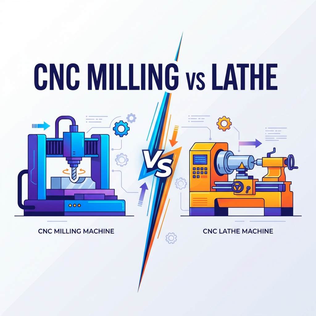 Compare CNC milling vs. turning. Learn differences in kinematics, geometry, cost, and automation to select the right machine for your production.Product news


