



In the field of precision machining, there are two types of CNC machines responsible for handling the vast majority of metal cutting tasks: CNC milling machines and CNC lathes. Although both remove material through subtractive manufacturing, they exhibit significant differences in mechanical structure, kinematic characteristics, and ideal workpiece geometry. Understanding these technical distinctions is crucial for making informed decisions in the workshop.
Core mechanical differences:
In a CNC milling machine, the cutting tool rotates while the workpiece remains stationary or moves linearly along the X, Y, and Z axes. The rotating tool (usually an end mill, face mill, or ball end mill) shears material as it cuts into the workpiece.
In a CNC lathe, the workpiece rotates at high speed, while the stationary tool fixed on the tool turret or tool post is fed into the material to remove chips. The main cutting motion comes from the rotation of the spindle, not the rotation of the tool.
Workpiece geometry:
CNC lathes are naturally capable of producing axisymmetric parts - components whose geometric shapes are symmetrical around a central axis. Common examples include shafts, bushings, pulleys, threaded rods, and bearing journals. Any feature that can be defined by a contour that rotates around a centerline is well-suited for turning processes.
CNC milling machines excel in machining prismatic parts - components featuring flat surfaces, grooves, slots, steps, and non-cylindrical shapes. Engine brackets, mold cavities, manifold bodies, and structural frames are typical milling application scenarios.
Many practical parts require both of these processes to be performed simultaneously. A shaft may need to have keyways milled along its length. A flange may need to have its outer diameter turned and bolt holes drilled on its surface. In such cases, a multi-task CNC machining center equipped with a movable tool can complete both turning and milling in a single setup, eliminating the need to transfer the part between machines.
Machine structure and shaft configuration
CNC milling machines are constructed around a fixed workpiece table and a moving spindle. In a vertical machining center, the spindle is oriented vertically and moves in the Z-axis direction, while the worktable is responsible for movement in the X-axis and Y-axis. In a horizontal machining center, the spindle is placed horizontally, which facilitates chip evacuation during heavy cutting. The spindle is supported by precision bearings and driven by a servo motor. For aluminum, its rotational speed can exceed 10,000 rpm, while for steel, it ranges from 4,000 to 6,000 rpm.
Whether to choose a CNC milling machine or a CNC lathe ultimately depends on the geometry of the part and production requirements. For parts with a completely prismatic shape, a milling machine is essential. For parts primarily with circular shapes, a lathe is the right choice. When a component requires both cylindrical and non-cylindrical features, a turning center equipped with live tooling or a complete five-axis CNC machining center can integrate these two processes into one workflow. For more information about our products, please contact our team!
Related Articles
-
 Dear Customers and Business Partners,In order to strictly comply with national export control laws and regulations, and to fulfill international obligations, ensuring that our exported CNC milling machines and CNC lathes are fully legal and compliant, we hereby notify you of the relevant policies coCompany News
 -
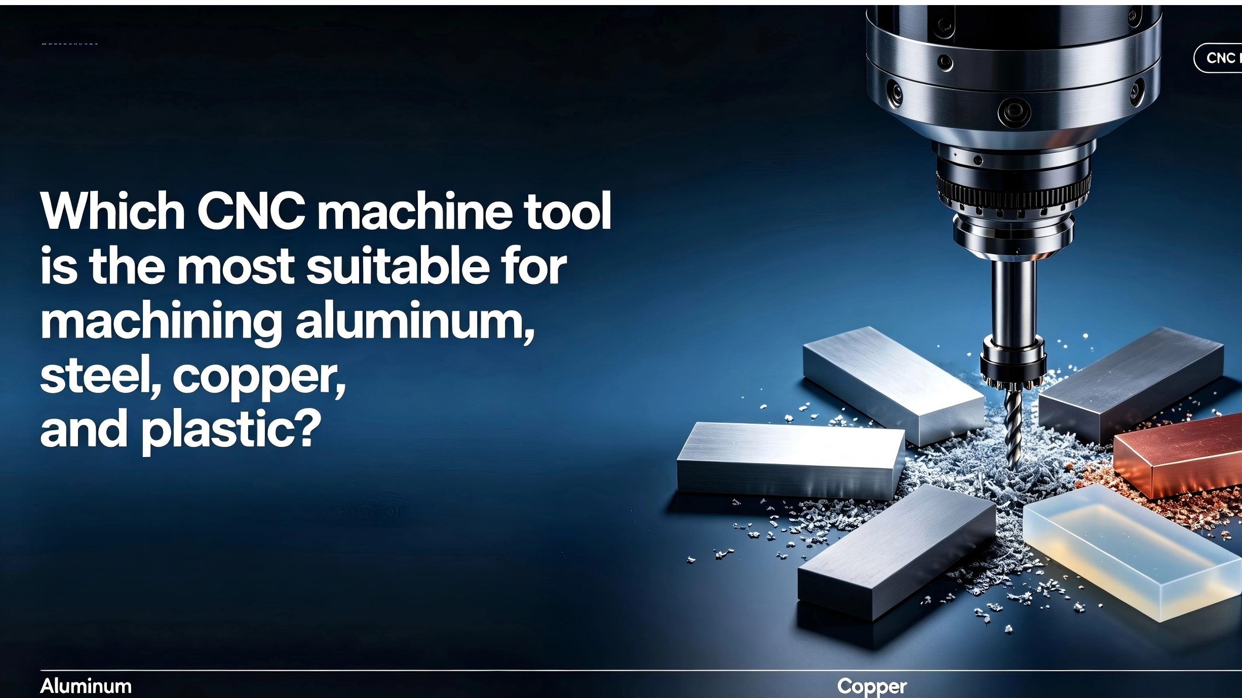 Understanding which machine tool is best suited for machining which material can assist machining factories and machine tool agents in making the optimal choice. This article introduces the materials that can be most effectively machined by CNC milling machines, CNC lathes, and CNC machining centers.CNC Machine Industry News
 -
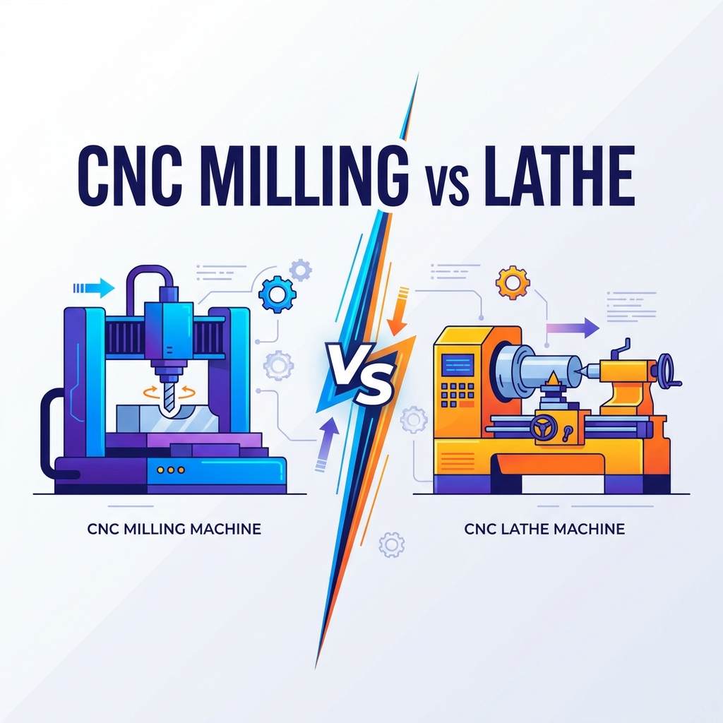 Compare CNC milling vs. turning. Learn differences in kinematics, geometry, cost, and automation to select the right machine for your production.Product news
