



Multi-setup operations drain manufacturing profitability. Machining complex, five-sided parts on standard 3-axis equipment forces operators into a cycle of manual part flipping. Every time a workpiece is unclamped, repositioned, and reclamped, you introduce tolerance stacking. Precision degrades. Idle spindle time increases. Throughput bottlenecks at the machine while operators wrestle with multiple fixtures.
Traditional setups require dedicated fixtures for every face of the part. This approach demands excessive operator intervention and drastically reduces overall equipment effectiveness. The core problem remains relational accuracy. When features on different faces must hold tight geometric tolerances to one another, manual repositioning introduces unacceptable error margins.
Enter the specialized hybrid architecture that bridges the gap between vertical and horizontal platforms. This guide objectively evaluates when the capital expenditure of a combined architecture makes sense over traditional vertical machining centers, horizontal machining centers, or standard rotary add-ons.
Setup Reduction: Consolidating operations into a single setup for five-sided machining eliminates tolerance stacking errors inherent in manual part repositioning.
Architectural Trade-offs: While offering superior versatility, combined machining centers introduce unique programming complexities and potential rigidity compromises compared to dedicated, single-spindle monolithic machines.
Cost-to-Volume Ratio: The ROI of a vertical horizontal machining center peaks in high-mix, low-to-medium volume environments where fixture changeover times severely impact profitability.
Chip Management: Unlike standard VMCs, the horizontal capability of a combined machine leverages gravity for superior chip evacuation during deep pocketing and large-hole boring.
Defining the Vertical Horizontal Machining Center
Architectural Overview
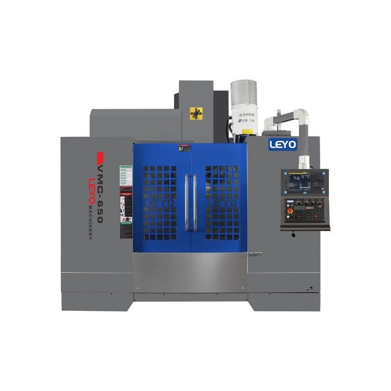
A combined machining center merges two distinct machining philosophies into a single footprint. The mechanics rely on advanced spindle kinematics rather than simply rotating the workpiece. Most configurations utilize an articulating spindle head that rotates from a vertical Z-axis orientation to a horizontal Y-axis or X-axis orientation. Other designs employ dual-spindle configurations, where a vertical ram and a horizontal spindle share the same massive cast-iron column. This architecture allows the cutting tool to approach the workpiece from orthogonal angles without moving the part itself.
The machine frame must accommodate the swept volume of the articulating head. This requires a larger internal work envelope compared to a standard VMC. The articulation is typically driven by a high-torque rotary axis built directly into the ram or the spindle housing. Once positioned, heavy-duty hydraulic clamps or Hirth couplings lock the head rigidly in place. This mechanical locking mechanism ensures the spindle can withstand heavy milling forces without deflecting or inducing chatter into the workpiece.
Differentiation from 5-Axis
You must distinguish between positional multi-face machining and simultaneous 5-axis contouring. A vertical horizontal machining center primarily executes 3+2 machining. The spindle rotates to a specific vector, locks into position, and performs standard 3-axis toolpaths on that specific face. It does not continuously interpolate the rotary axes while the tool is engaged in the material.
Simultaneous 5-axis machines continuously move all five axes to machine complex, sweeping surfaces like aerospace impellers or turbine blades. While some combined machines offer simultaneous capabilities, their primary design intent is positional access. Locking the articulating head provides superior rigidity for heavy roughing, drilling, and boring operations compared to a continuously interpolating rotary axis that relies solely on servo motors to hold position.
Core Use Case
Specific part topologies benefit immensely from this hybrid architecture. The ideal candidates are complex prismatic parts. Think of cast iron engine blocks, gearbox housings, hydraulic manifolds, and large pump casings. These components require heavy face milling, deep hole drilling, and precision boring on multiple orthogonal faces.
Processing a hydraulic manifold on a standard VMC requires at least six setups. You must machine the top, flip it four times for the sides, and flip it once more for the bottom. A combined machine handles the top and all four sides in a single setup. The operator only handles the part twice. This drastically reduces fixture complexity, eliminates custom soft jaws, and slashes setup time.
Success Criteria for Five-Sided Machining
Precision and Tolerance Stacking
Every manual part transfer introduces microscopic errors. A single aluminum chip caught under a fixture plate, slight variations in vise clamping pressure, or minor datum shifts all contribute to tolerance stacking. When you machine a bearing bore on one face that must perfectly intersect a fluid channel on an adjacent face, relational accuracy dictates part success or failure.
Eliminating the physical flip solves this. By keeping the workpiece clamped in a single zero-point fixture, the machine's absolute positioning dictates the relational accuracy between features. The spindle moves, but the part remains static. This guarantees that orthogonal features align perfectly. You rely on the machine's linear glass scales rather than the operator's ability to indicate a part flat and square.
Cycle Time vs. Takt Time
Do not confuse in-cut cycle time with overall takt time. A dedicated HMC might rough a steel casting faster due to sheer spindle power and a monolithic column. However, if that part requires secondary operations on a VMC to finish the top face, the overall takt time skyrockets. The part sits on a cart in a queue waiting for the next machine to open up.
Uninterrupted spindle time dictates production schedules. A combined machine might have a slightly longer in-cut cycle time for specific heavy roughing passes, but it delivers a finished part in one continuous operation. You eliminate queue times, secondary setup times, and the labor required to move parts across the shop floor.
Labor Utilization
Operator-dependent setups strangle throughput. If a machine cycle lasts ten minutes, the operator is tethered to that machine, constantly loading, unloading, and blowing off chips. This prevents them from managing other equipment, inspecting parts, or prepping the next job.
Consolidating operations shifts the paradigm to unattended or lightly attended machining. A single setup that machines five sides might run for two straight hours. This long cycle time frees the operator to manage a secondary cell. Labor utilization improves dramatically when operators manage manufacturing processes rather than babysitting vises.
Comparing Equipment for Multi-Face CNC Machining
Evaluating the right equipment requires a direct comparison of capabilities, limitations, and ideal applications. Below is a breakdown of how standard VMCs with rotary tables, dedicated HMCs, and combined architectures stack up against one another.
| Machine Configuration | Primary Advantages | Core Limitations | Best Fit Application |
|---|---|---|---|
| Standard VMC + 4th/5th Axis Trunnion | Lower initial capital expenditure. Familiar programming environment for operators. Superior operator visibility and ergonomic access to the workpiece for quick changeovers. | Limited Z-axis clearance. The trunnion consumes significant vertical space. Poor chip evacuation in deep cavities. Potential clearance issues between the spindle housing and the trunnion table. | Small, complex parts. Low-volume prototyping. Aluminum and soft materials where extreme rigidity is not required. |
| Dedicated Horizontal Machining Center (HMC) | Exceptional rigidity for tough materials. Optimal chip clearing via gravity. Tombstone fixturing allows multiple parts to be loaded. Pallet pools enable offline setup. | High footprint and significant capital investment. Limited access to the top face of the part. Machining the top face often requires specialized fixturing or a secondary VMC operation. | High-volume production. Heavy roughing of cast iron, steel, and aerospace alloys. Long-run automotive or aerospace contracts. |
| Combined Machining Center (Vertical/Horizontal) | True five-sided machining access in one setup. Combines heavy face milling capability with deep boring efficiency. Keeps heavy, awkward parts stationary. | Higher mechanical complexity. Requires advanced CAM software and highly accurate post-processors. Higher maintenance overhead due to articulating joints. | High-mix prismatic parts. Heavy castings. Job shops dealing with frequent changeovers and complex orthogonal features. |
Evaluation Dimensions: When the Vertical Horizontal Configuration Wins
High-Mix, Low-Volume Production
Job shops thrive on flexibility. When you process a different part number every day, dedicated tombstone fixtures become a massive liability. The setup time required to populate an HMC tombstone destroys the profit margin on a run of five parts. A combined machine excels in this high-mix environment. You can utilize simple zero-point vises or dovetail fixtures to grab the bottom 0.100" of the raw stock. The articulating head then reaches the remaining five sides. This flexibility allows job shops to pivot quickly between vastly different part geometries without engineering complex, dedicated workholding.
Floor Space Constraints (Footprint ROI)
Shop floor real estate is expensive. Housing a dedicated VMC for face milling and a dedicated HMC for deep boring consumes massive square footage. You must also account for the work-in-progress staging area between the two machines, tool carts, and operator walkways. Replacing two separate machines with a single vertical horizontal unit reclaims valuable floor space. While a combined machine has a larger footprint than a single VMC, it is significantly smaller than two separate machining cells. This consolidation streamlines material flow and reduces WIP inventory cluttering the aisles.
Complex Prismatic Parts
Prismatic parts often require conflicting machining strategies. A large gearbox housing might need heavy vertical face milling with a 4-inch shell mill to establish a flat mating surface. Immediately after, it requires deep, precision horizontal boring for the bearing journals. Doing this on a VMC requires long, unstable boring bars and fighting chip evacuation. Doing it on an HMC makes the top face milling difficult and often requires an angle head attachment, which lacks rigidity. The combined architecture tackles both optimally. The vertical orientation handles the heavy face cuts, and the horizontal orientation allows gravity to clear chips during the deep boring cycles.
Heavy Workpieces
Rotating a 2,000-pound casting on a 4 axis machining center introduces massive inertial loads. The rotary table must fight gravity and momentum, which can compromise positioning accuracy, wear out rotary bearings, and induce vibration during heavy cuts. Keeping large, heavy parts stationary is inherently more stable. A combined machine secures the heavy workpiece to a rigid, fixed T-slot table. The lighter spindle head articulates around the part. This approach maintains superior dynamic stiffness and ensures precise feature location on massive components.
Material Types and Machinability
Material properties dictate machine selection. Tough aerospace alloys like Titanium 6Al-4V or Inconel 718 demand extreme rigidity to prevent chatter, tool deflection, and catastrophic insert failure. Dedicated HMCs typically excel here due to their monolithic column designs and CAT50 or HSK100 tapers. However, modern combined machines utilize massive cast iron frames and heavy-duty curvic couplings to lock the articulating head. This provides near-HMC rigidity. When machining standard 6061 aluminum or 1018 mild steel, the combined machine effortlessly handles high-speed roughing while offering superior access to all faces.
Implementation Realities and Adoption Risks
CAM Software and Post-Processor Requirements
You cannot run a combined machine with basic 3-axis CAM software. The machine requires advanced toolpath generation to manage the articulating head, define tool vectors, and ensure collision-free transitions between faces. Upgrading CAM packages represents a hidden operational cost. Furthermore, you need a flawless post-processor. The post-processor translates the CAM data into specific G-code for your machine's kinematics, handling commands like G68.2 tilted work planes. Developing and proving out a post-processor for articulating heads requires close collaboration with the machine tool builder and the CAM vendor.
Workholding and Fixturing
Securing a part rigidly enough for heavy milling while leaving five sides exposed is the primary challenge of multi-face CNC machining. Traditional 6-inch Kurt vises block access to the sides of the part. You must adopt modern workholding strategies to succeed.
Implement zero-point clamping systems to elevate the part off the machine table, providing clearance for the spindle housing.
Utilize dovetail fixtures to grip the raw stock securely using only a fraction of an inch of material at the base.
Deploy low-profile 5-axis self-centering vises for smaller prismatic parts to maximize tool access.
Design custom tombstone-style risers for tall parts to bring the machining zone closer to the spindle's natural pivot point.
Tool Magazine Capacity
Consolidating multiple operations into a single setup inherently demands a larger tool library. You are no longer just face milling; you are drilling, tapping, boring, and chamfering five different sides. A standard 24-tool automatic tool changer will bottleneck your process. Operators will waste time manually swapping tools mid-cycle. You must evaluate the combined machine's ATC capacity. A minimum of 60 to 120 tools is often required to support true single-setup, unattended operations. You also need capacity for redundant sister tooling to automatically swap out worn roughing endmills during long cycles.
Operator Ergonomics and Visibility
True five-sided access often comes at the expense of operator visibility. Articulating heads and massive machine enclosures can obstruct the operator's view of the cutting zone. This creates anxiety during program prove-outs. Operators need to see the tool engage the material to verify feeds, speeds, and clearances. You must balance the need for access with safety. Look for machines with large viewing windows, internal washdown hoses, high-definition internal camera systems, and ergonomic control pendants that allow the operator to safely monitor the process from outside the splash guard.
Maintenance and Spindle Rigidity
Moving parts wear out. An articulating spindle head introduces mechanical complexity that a fixed-spindle VMC lacks. The rotary joints, locking mechanisms, hydraulic lines, and internal cabling are subjected to constant stress, vibration, and coolant exposure. You must objectively evaluate the mechanical wear on these components. While high-end machines use robust Hirth couplings to lock the head and maintain rigidity, the maintenance overhead will be higher than a simple 3-axis machine. Preventative maintenance schedules, including regular geometry checks and ballbar testing, must be strictly enforced to prevent unexpected downtime.
Operator Training
The learning curve for multi-face machining is steep. Operators accustomed to standard Cartesian coordinates must now understand tool vectors, dynamic work offsets, and tool center point control. They must visualize how the machine's kinematics affect tool clearances and approach angles when the head tilts 90 degrees. Training is non-negotiable. You must invest in comprehensive training programs to ensure your operators can safely set up, program, indicate parts, and troubleshoot these complex machines without causing catastrophic spindle collisions.
Cost-to-Value Analysis: Justifying the Investment
CapEx vs. OpEx
A combined machining center carries a higher initial purchase price than a standard VMC. However, you must evaluate this against the reduction in operational expenditures. Consolidating setups drastically reduces fixture design and manufacturing costs. You no longer need three custom aluminum soft jaws for every part number. Furthermore, reducing manual part handling slashes labor hours and minimizes the risk of operator-induced scrap. The higher CapEx is offset by leaner, more predictable OpEx and faster part delivery times.
Spindle Utilization Rates
Standard VMCs running multi-setup parts often hover around 30% to 40% spindle uptime. The rest of the time is spent loading, unloading, cleaning fixtures, blowing off chips, and indicating parts. Moving to a single-setup architecture can push spindle utilization past 70%. When calculating ROI, factor in the value of doubling your spindle uptime. You are producing twice as many parts per shift without adding headcount, expanding your facility, or buying a second machine.
Scrap Reduction
Scrap happens during secondary operations. An operator fails to clean a chip out of a vise, misaligns a datum edge, or clamps the part too hard and distorts the geometry. When you machine a high-value casting, scrapping it on the final operation is financially devastating. By completing the part in one setup, you eliminate the primary variables that cause scrap. The financial impact of reducing scrap rates on complex components often justifies the machine investment alone, especially in aerospace or medical manufacturing.
Conclusion
Take these actionable steps before making a capital equipment decision:
Conduct rigorous time-studies on your most problematic five-sided parts to quantify the exact cost of your current secondary setups and queue times.
Request live test cuts from machine tool builders using your specific part geometry and toughest material to verify rigidity, surface finish, and cycle times.
Audit your current CAM software capabilities and ensure your vendor can provide a proven, collision-free post-processor for articulating kinematics.
Evaluate your tool magazine requirements to ensure the new machine can support unattended, single-setup operations without manual tool swaps.
FAQ
Q: What is a vertical horizontal machining center?
A: It is an advanced CNC machine equipped with an articulating spindle head or dual spindles. This design allows the machine to perform both vertical and horizontal milling, drilling, and boring operations on a stationary workpiece in a single setup.
Q: How does a 4 axis machining center compare to a combined machining center?
A: A 4-axis machine rotates the workpiece to present different faces to a fixed spindle. A combined machine keeps the workpiece stationary and articulates the tool around it. This provides better tool clearance and true 5-sided access without requiring complex rotary fixtures.
Q: What are the main limitations of five-sided machining on a combined machine?
A: The primary limitations include workholding challenges, as you must secure the part rigidly while exposing five sides. Additionally, the mechanical complexity of the articulating head requires advanced maintenance, and the bulky spindle housing can obstruct operator visibility.
Q: Does a vertical horizontal machine save floor space?
A: Yes. While a combined machine has a larger footprint than a single standard VMC, it typically consumes significantly less floor space than housing both a dedicated vertical cell and a dedicated horizontal cell, along with the required staging areas between them.
Q: How does chip evacuation work on a combined machining center?
A: Operators program heavy cavity milling and large-hole boring using the horizontal spindle orientation. This allows chips to fall away naturally via gravity, preventing the cutter from recutting chips, which extends tool life and improves surface finish.
Q: Can a combined machining center perform simultaneous 5-axis machining?
A: While some high-end models offer simultaneous 5-axis contouring, many are designed primarily for 3+2 positional machining. The spindle rotates to a specific angle, locks rigidly into place, and executes standard 3-axis toolpaths on that face.
Related Articles
-
 Dear Customers and Business Partners,In order to strictly comply with national export control laws and regulations, and to fulfill international obligations, ensuring that our exported CNC milling machines and CNC lathes are fully legal and compliant, we hereby notify you of the relevant policies coCompany News
-
 Abrasive graphite dust destroys standard CNCs. Learn why specialized dust-proof machines and proper wet or dry milling methods are essential for safe EDM electrode production.Product news
-
 Drill tap centers deliver high-speed threading for high-volume production. Understanding spindle torque limits prevents costly tool breakage and optimizes machine cycle times.Product news


