



The baseline accuracy of any machining operation is strictly limited by the stability of the workpiece. Spindle speed, advanced CNC controls, and premium cutting tools mean nothing if the part moves during the cut. Inadequate workholding leads directly to part deflection, chatter, and tolerance stack-up. These issues ultimately cause high scrap rates and compromised profit margins in precision manufacturing. You must match your workholding strategies to specific part geometry, material properties, and production volume. This targeted approach is the only way to fully leverage the capabilities of a modern vertical milling machine.
Rigidity Dictates Precision: The primary function of workholding is to eliminate vibration and resist cutting forces; selecting the wrong method introduces micro-movements that destroy tight tolerances.
Geometry Drives Selection: Standard precision vises suit prismatic parts, while thin-walled, cylindrical, or complex organic shapes require specialized vacuum, magnetic, or custom fixturing.
Setup Time vs. Cycle Time: High-mix, low-volume operations demand modular, quick-change workholding, whereas high-volume production justifies the upfront cost of dedicated custom fixtures.
Clamping Distortion is a Hidden Flaw: Over-clamping to secure a part can induce mechanical stress, causing the workpiece to spring out of tolerance once released from the fixture.
The Role of Workholding in a Vertical Milling Machine
Defining Accuracy: Repeatability vs. Rigidity
Holding a part securely under heavy loads defines rigidity. Locating a part in the exact same position every single time defines repeatability. Both factors dictate the overall capability of the machine setup. A highly rigid setup prevents the part from vibrating during aggressive roughing passes, allowing you to push chip loads to the tool's maximum limit. A highly repeatable setup ensures that the fiftieth part measures exactly the same as the first part without requiring the operator to re-indicate the datums. Operators must balance both elements. Failing to secure the part rigidly destroys cutting tools and spindle bearings. Failing to locate the part repeatably destroys dimensional tolerances and creates bottlenecks in the quality control department.
Common Causes of Deflection and Tolerance Creep
Cutting forces generated by the spindle are intense and multidirectional. A standard drill press applies primarily axial loads straight down into the table, which naturally compresses the part into the fixture. A mill requires heavy lateral and radial forces to cut accurate slots and pockets. Climb milling, the preferred method for surface finish and tool life, actively tries to pull the workpiece into the cutter. Improper clamping vectors fail to resist these lateral forces. Insufficient contact area between the jaw and the workpiece leads to chatter. Chatter causes poor surface finish and dimensional inaccuracies during high-speed lateral cuts. Tolerance creep happens when micro-movements push the part slightly out of alignment during heavy tool engagement, often going unnoticed until the final inspection phase.
The Impact of Machine Condition and Toolholding Synergy
Workholding cannot compensate for degraded machine ways. Poor machine leveling inherently twists the machine base, throwing off alignment and causing the table to tram out of square. An unmaintained, unstable worktable destroys the foundation of any fixture. You must stone the table with a precision ground stone to remove microscopic burrs before mounting any vise or plate. Wipe the table down with a light coat of way oil to prevent rust under the fixture. Workholding and toolholding share a critical operational link. Perfect fixturing is completely negated if the spindle taper introduces excessive runout. Standard tapers like CAT40, BT40, or R8 must remain clean and undamaged. Precision tool holders must grip the cutting tool securely to prevent vibration transfer down into the clamped workpiece. Check your drawbar tension annually; a weak drawbar allows the toolholder to pull out, ruining the part regardless of how well it is clamped.
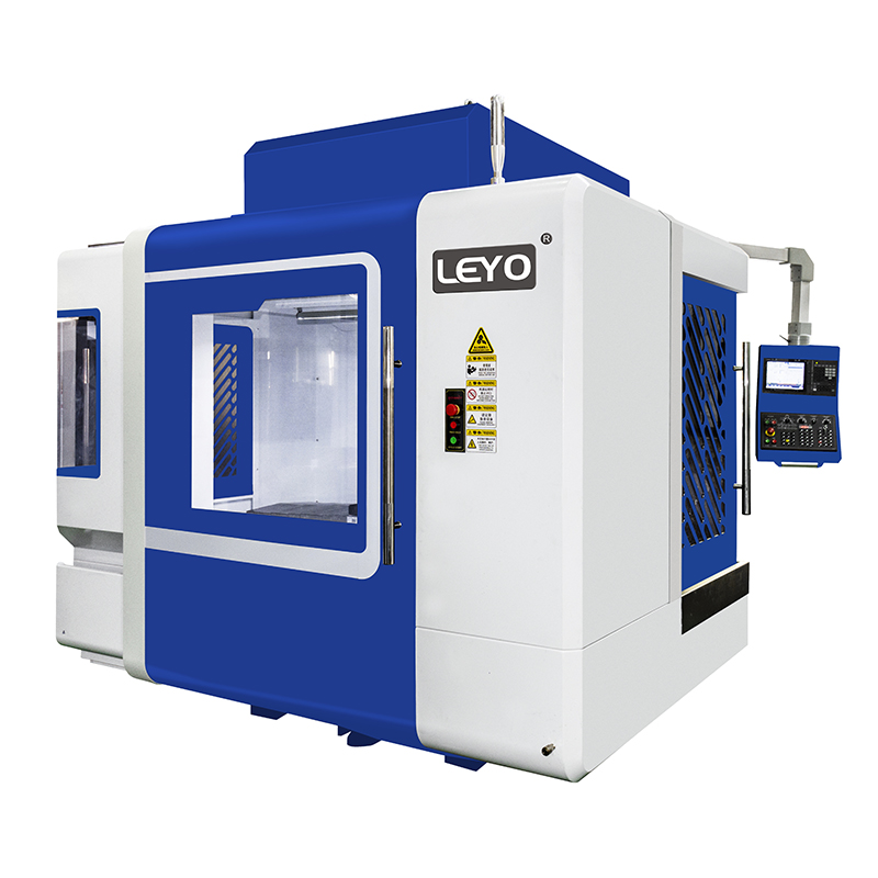
Core Workholding Methods for the Vertical CNC Milling Machine
Precision Machine Vises (The Industry Standard)
Standard Kurt-style and CNC-specific vises remain the industry standard for securing prismatic parts. These vises utilize an angled jaw design to pull the workpiece down during clamping. This mechanism prevents jaw lift and keeps the part seated flat against the parallels. Matched vise sets are necessary for holding long components across the table, requiring the beds of both vises to be ground to the exact same height. The setup phase requires absolute precision. Use magnetic bases and dial test indicators to tram the fixed jaw perfectly square to the machine axes. Bolt the vise down, leave one side slightly snug, sweep the fixed jaw with the indicator, and tap it into zero with a dead-blow hammer before final torquing. The primary trade-off involves high rigidity and versatility versus severe limitations when gripping non-prismatic or oversized parts.
Modular Fixturing, Clamping Kits, and Step Blocks
T-slot tables allow direct clamping of large or irregularly shaped castings. Clamping kits utilize T-nuts, threaded studs, flange nuts, step blocks, and strap clamps to secure heavy workpieces. Proper clamp positioning dictates the success of this method. Place the strap clamp closer to the workpiece than the step block. This geometry maximizes downward force and prevents the clamp from slipping backward under heavy vibration. Always ensure the stud is threaded fully into the T-nut to prevent stripping the threads out of the machine table. The trade-off here is extreme flexibility versus lengthy, manual setup times. Manual clamping reduces spindle uptime and increases the risk of operator error during changeovers. You must also program careful toolpaths to avoid crashing the spindle into the strap clamps.
Soft Jaws and Custom Fixture Plates
Machining aluminum or steel soft jaws allows shops to encapsulate complex part profiles securely. Operators mill the exact negative shape of the workpiece directly into the jaws. To do this correctly, place a spacer between the jaws, clamp down to pre-load the vise screw, and then machine the pocket. This ensures the jaws grip the part with the exact same pressure dynamics used during machining. This provides massive surface contact and prevents marring on finished surfaces. Dedicated fixture plates reduce changeover times drastically in high-production environments. Use precision dowel pins to locate the plates repeatedly on the machine table. Zero-point clamping systems allow operators to swap entire fixture plates in seconds using pneumatic pull studs. These systems provide excellent return on investment by maximizing green-light machining time.
Vacuum Chucks and Magnetic Workholding
Vacuum systems excel at holding thin, flat substrates without inducing any clamping stress. Aerospace aluminum panels require vacuum workholding to prevent bowing during facing operations. A grid plate uses rubber gasket cord to isolate the vacuum zone directly under the part. High-flow venturi generators pull the part flat against the rigid aluminum plate. Magnetic chucks secure ferrous materials while providing full five-sided access to the workpiece. Operators can machine the entire profile without moving clamps or programming avoidance zones. The trade-off involves excellent access and zero clamping distortion versus limited holding force. Magnetic and vacuum systems struggle against heavy lateral cuts and require lighter, high-speed machining strategies with smaller step-overs.
Rotary Tables and Indexers (4th Axis Integration)
Adding a rotary axis to a 3-axis vertical CNC milling machine drastically improves overall accuracy. Rotary tables allow multiple faces to be machined in a single setup. This eliminates the tolerance stack-up caused by manual repositioning and flipping parts. Integrating a 4th axis maximizes multi-axis capability and reduces handling time. Mount a trunnion table between the rotary indexer and an A-frame tailstock to hold multiple vises or a custom tombstone. You must tram the rotary axis perfectly parallel to the X-axis and find the exact center of rotation to ensure your G54 work offsets track correctly as the part rotates.
Workholding Application Matrix
| Method | Ideal Material Profile | Setup Speed | Rigidity Rating |
|---|---|---|---|
| Precision Vise | Prismatic, square stock | Fast | Very High |
| Step Blocks & Strap Clamps | Large castings, odd shapes | Slow | High |
| Machined Soft Jaws | Complex profiles, 2nd operations | Medium | High |
| Vacuum Chucks | Thin aluminum, plastics, composites | Fast | Low |
| Magnetic Chucks | Thick ferrous plates, steel blocks | Fast | Medium |
Evaluating Workholding for a Precision Vertical Milling Center
Matching Method to Tolerance Requirements
Select your workholding based strictly on the Geometric Dimensioning and Tolerancing (GD&T) requirements. Flatness, parallelism, and true position dictate how the part must be held. Datum structures on the blueprint must dictate how the part is located and clamped in the machine. Apply the 3-2-1 locating principle: three points define the primary datum plane, two points define the secondary datum line, and one point defines the tertiary datum stop. If a surface is a primary datum, it must rest against a fixed, rigid locator, not a movable jaw. Faster spindle speeds and advanced CNC controls amplify the need for ultra-rigid workholding. Aggressive indexable cutting tools require absolute stability to prevent catastrophic insert failure. A precision vertical milling center will only hold tenths if the part is locked down according to its datum reference frame.
Analyzing Setup Time vs. Machining Time (ROI)
Compare the labor costs of manual dial-in against the capital expenditure of quick-change systems. Manual setups consume hours of potential machining time. Dialing in a four-jaw chuck or tramming a large casting takes a skilled machinist away from running parts. Zero-point workholding systems require a higher initial investment but pay off rapidly through increased spindle uptime. Calculate the break-even point of custom fixturing by dividing the fixture cost by the time saved per part. High-volume runs easily justify expensive, dedicated hydraulic fixtures. Implement Single-Minute Exchange of Dies (SMED) principles on your CNC floor. Pre-stage all fixtures, tools, and programs while the machine is still running the previous job.
Scalability and Automation Readiness
Hydraulic and pneumatic clamping systems suit environments transitioning toward automated machine tending. Robotic part loading requires predictable, repeatable clamping actuation. Manual vise handles do not work with robotic arms. Upgrading to programmable workholding prepares the shop floor for lights-out manufacturing operations. Use hydraulic work supports that spring up to contact the rough casting surface and then lock rigidly in place. This prevents distortion on uneven cast surfaces while providing massive support against cutting forces. Route pneumatic lines through the machine table to actuate toggle clamps automatically via M-codes in the part program.
Specialized Applications: Vertical Mill for Mold Machining
Managing Heavy Tool Loads in Tool and Die Work
Roughing hardened tool steels like P20 or H13 requires extreme rigidity. High-feed milling strategies generate massive cutting forces that push back against the spindle and the fixture. Heavy-duty, low-profile clamping minimizes vibration during deep cavity machining. Tall fixtures act like tuning forks and amplify chatter. Keep the workpiece as close to the machine table as physically possible. When using a vertical mill for mold machining, ensure your clamps do not interfere with the toolholder during deep Z-axis moves. Use low-profile toe clamps that grip the very bottom edge of the mold base, leaving the entire top surface clear for the spindle housing to clear.
Thermal Expansion and Clamping Distortion Risks
Prolonged machining cycles in mold making generate immense heat. This heat transfers directly into the workpiece, causing part expansion. Workholding strategies must accommodate this thermal growth without warping the mold base. Rigidly pinning a large aluminum or steel plate on all four sides will cause it to bow upward as it heats. Rely on stress-relieving fixture designs. Use sliding clamps or guided locators that allow linear expansion along one axis while maintaining datum accuracy on the primary locating pin. Flood coolant helps manage the temperature, but the fixture itself must mechanically allow for thermal slip.
Implementation Risks and Mitigation Strategies
Risk: Over-Clamping and Part Deformation
Operators often over-tighten vises to prevent part movement during heavy cuts. This excessive force permanently yields thin-walled parts. The machine cuts the part flat while it is under stress. The part springs out of tolerance the moment the vise opens. Implement torque wrenches for all manual vise handles to standardize clamping force across all shifts. Utilize programmable hydraulic pressure for consistent gripping. Switch to encapsulated soft jaws to distribute the clamping force over a much larger surface area. For delicate parts, machine a relief pocket in the soft jaws so the clamping pressure only applies to the strongest sections of the geometry.
Risk: Chip Evacuation and Coolant Interference
Complex fixtures easily trap metal chips. Trapped chips lead to recutting, rapid tool wear, or catastrophic tool breakage. Chips resting on locating surfaces prevent the proper seating of the next part, causing immediate scrap. Design custom fixtures with steep chip wash-out channels. Eliminate flat pockets where chips accumulate. Integrate through-spindle coolant or programmable air blasts to clear the work zone automatically before the next tool engages. Install washdown hoses and mandate that operators thoroughly spray down the fixture between every single cycle.
Risk: Degradation of Workholding Accuracy
Vises and fixtures wear down over time. They lose their tram, squareness, and flatness through repeated use, overtightening, and minor collisions. Establish a strict preventative maintenance schedule for all workholding devices. Regularly indicate fixed jaws to verify alignment. Check the machine table for burrs and stone it flat daily. Periodically re-skim custom fixture plates on the machine to restore absolute flatness and parallelism. Disassemble precision vises annually to clean the thrust bearings, inspect the screw for wear, and re-grease the moving components.
Conclusion
Maximizing accuracy requires treating workholding as an integral component of the machining system. It is equal in importance to the cutting tool, the toolholder, and the machine tool itself. Precision vises and modular clamping make the most sense for high-mix, low-volume job shops. Zero-point systems and custom machined soft jaws provide the best return for low-mix, high-volume production environments. Vacuum and magnetic systems remain the top choice for specialized thin-wall or surface-critical applications. Take the following steps to improve your shop floor accuracy immediately:
Audit your current scrap rates to identify specific parts failing due to clamping distortion, chatter, or poor repeatability.
Implement torque wrenches on all manual vises to eliminate operator-induced over-clamping.
Stone your machine tables and sweep your fixed vise jaws with a dial indicator before starting any high-tolerance job.
Consult with tooling engineers to pilot a zero-point quick-change system on your most problematic, high-changeover setup.
FAQ
Q: What is the most accurate workholding method for a vertical milling machine?
A: Accuracy depends entirely on the part geometry. However, zero-point fixturing combined with custom machined soft jaws generally offers the highest repeatability for complex parts. This method encapsulates the part profile, maximizes surface contact, and allows rapid changeovers with sub-micron positional accuracy.
Q: How does clamping force affect milling tolerances?
A: Excessive clamping force causes part deflection during machining. The machine cuts the part flat while it is under stress. Once released from the fixture, the material springs back to its natural state. This hidden distortion destroys flatness, parallelism, and true position tolerances.
Q: When should I use soft jaws instead of standard hard jaws?
A: Use soft jaws for holding irregular shapes, castings, or cylindrical parts. They are mandatory for secondary operations requiring exact encapsulation. Soft jaws also prevent marring or scratching on previously finished surfaces, ensuring cosmetic quality remains intact.
Q: Can workholding reduce chatter in a precision vertical milling center?
A: Yes. Maximizing surface contact area and clamping as close to the cutting zone as possible drastically increases rigidity. This dampens vibration and eliminates chatter. Using low-profile fixtures keeps the cutting forces close to the machine table, further increasing stability.
Q: What is a zero-point clamping system?
A: A zero-point clamping system is a modular quick-change platform. It uses precision retention knobs and pneumatic or hydraulic receivers. It allows operators to swap entire fixtures or vises in seconds while maintaining sub-micron positional repeatability, drastically reducing setup time.
Q: How do I hold thin parts on a vertical mill without bowing?
A: Thin parts require stress-free workholding. Suggest using vacuum chucks to pull the part flat against a rigid plate. Alternatively, use double-sided fixturing tape or low-profile toe clamps combined with a perfectly flat, stress-free resting surface to prevent bowing.
Related Articles
-
 Dear Customers and Business Partners,In order to strictly comply with national export control laws and regulations, and to fulfill international obligations, ensuring that our exported CNC milling machines and CNC lathes are fully legal and compliant, we hereby notify you of the relevant policies coCompany News
-
 Abrasive graphite dust destroys standard CNCs. Learn why specialized dust-proof machines and proper wet or dry milling methods are essential for safe EDM electrode production.Product news
-
 Drill tap centers deliver high-speed threading for high-volume production. Understanding spindle torque limits prevents costly tool breakage and optimizes machine cycle times.Product news


